AN-1176: Component Footprints and Symbols in the Binary .Bxl File Format
Introduction
Analog Devices, Inc., provides symbols and footprints for components created in a single format, that is, a binary Xlator (.bxl) file. The .bxl files have been created using the Ultra Librarian tool offered by Accelerated Designs, Inc. A free version of the Ultra Librarian Reader is available online from the Accelerated Designs website.
Customers can download the Ultra Librarian Reader to open the component binary .bxl file. For example, Analog Devices has created a .bxl file for the ADM2587E isolated RS-485/RS-422 transceiver. This .bxl file webpage provides a link to download the Ultra Librarian Reader.
Once the .bxl file is opened, the Ultra Librarian Reader allows the footprint and symbol to be exported to one of many CAD toolsets, including Cadence® Allegro®, Allegro®OrCAD®, Accel15/PCAD 2xxx/Altium6, Mentor PADS®, PowerPCB, and Zuken, Inc., CADSTAR®.
These toolsets cover 97% of CAD users, and thus enable Analog Devices to offer component footprints and symbols to meet the vast majority of customer needs.
Importing a Binary File to the Ultra Librarian Reader and Exporting to a CAD Tool
The examples in this application note illustrate how the Ultra Librarian Reader is used with
- the ADM2587E isolated RS-485/RS-422 transceiver ADM2587EBRWZ.bxl file
- the ADM3053 signal and power isolated CAN transceiver ADM3053BRWZ.bxl file
- the ADN4697E multipoint, low voltage differential signaling (M-LVDS) transceiver ADN4697EBRZ.bxl file.
The ADM2587E is a fully integrated signal and power isolated RS-485/RS-422 data transceiver with ±15 kV ESD protection, which is suitable for high speed communication on multipoint transmission lines. The ADM2587E includes an integrated isolated dc-to-dc power supply (Analog Devices isoPower®), which eliminates the need for an external dc-to-dc isolation block. The device integrates the Analog Devices iCoupler® technology to combine a three-channel isolator, a three-state differential line driver, a differential input receiver, and isoPower.
The ADN4697E is a multipoint low voltage differential signaling (M-LVDS) transceiver (driver and receiver pair) that can operate at up to 200 Mbps (100 MHz). The receiver detects the bus state with a differential input of as little as 50 mV over a common-mode voltage range of −1 V to +3.4 V. ESD protection of up to ±15 kV is implemented on the bus pins.
The ADM3053 is an isolated controller area network (CAN) physical layer transceiver with an integrated isolated dc-to-dc converter. The device integrates iCoupler and isoPower technology. The ADM3053 creates a fully isolated interface between the CAN protocol controller and the physical layer bus. It is capable of running at data rates of up to 1 Mbps.
Importing and Exporting Examples
Importing and Exporting the ADM2587E Isolated RS-485/RS-422 Transceiver .BXL File
This section illustrates how to create a Cadence Allegro 15.2 or newer file from the ADM2587EBRWZ.bxl file.
- Download the .bxl file from the ADM2587E symbols and footprints page and then wait for the file to download.
- Open the Ultra Librarian Binary Reader (see Figure 1).
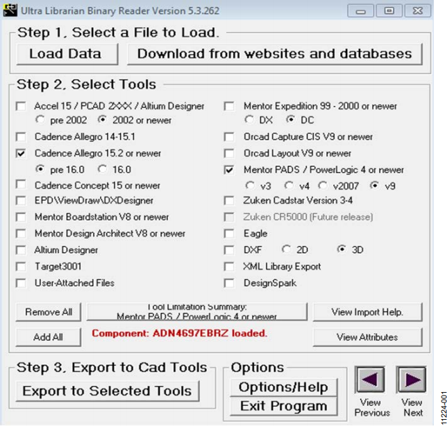
Figure 1. Importing a File to the Ultra Librarian Reader and Exporting to Cadence.
- Select Load Data.
- Navigate to the directory where you downloaded the ADM2587EBRWZ.bxl file.
This loads the tool with both a footprint and symbol window (see Figure 2).
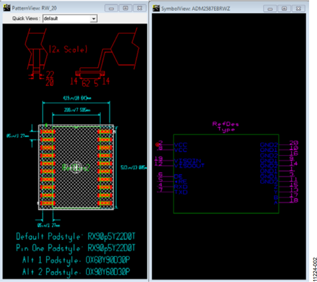
Figure 2. ADM2587E Isolated RS-485/RS-422 Transceiver Footprint and Symbol Window Using Ultra Librarian Reader.
- Both screens in Figure 2 can be zoomed by clicking within the black background using the left mouse button. Once the window is selected, pan by holding the right mouse button down, or zoom in and out using the + and − keys.
- Select the desired CAD tool from the listing provided in Figure 1. For this example, Cadence Allegro 15.2 or newer is selected.
- Select the Export to Selected Tools option. A text box log file similar to that shown in Figure 3 is then displayed. This displays the location of the exported files and provides guidance for importing the new library to Cadence Allegro 15.2 or newer.
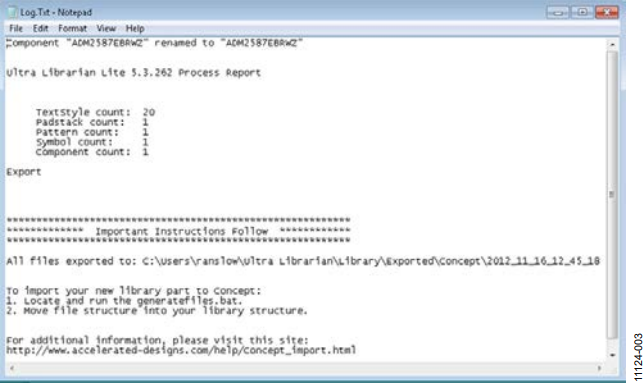
Figure 3. Exporting Files to Cadence Concept 15 or Newer Format and Importing to the Cadence Library.
- Copy the exported folder to the worklib folder for the Cadence project created.
- Locate the ADM2587E symbol in the project library and add it to your schematic.
Note that further instructions are provided by Accelerated Designs on the appropriate product page.
Figure 4 shows the ADM2587E symbol once imported and opened within Cadence Allegro 15.2 or newer.
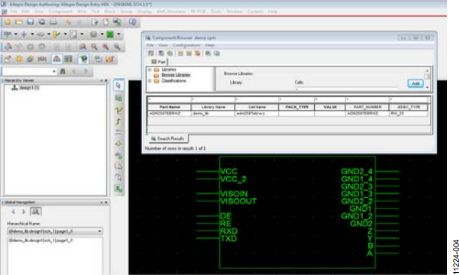
Figure 4. ADM2587E Isolated RS-485/RS-422 Transceiver Component Added and Displayed in Cadence.
Importing and Exporting the ADN4697E M-LVDS Transceiver .BXL File
This example illustrates how to create a Mentor PADS v9 file from the ADN4697EBRZ.bxl file.
- Download the .bxl file from the ADN4697E symbols and footprints page and then wait for the file to download.
- Open the Ultra Librarian Binary Reader (see Figure 1).
- Select Load Data as shown in Figure 1.
- Navigate to the ADN4697EBRZ.bxl file. Figure 5 shows the symbol and footprint for the ADN4697E.
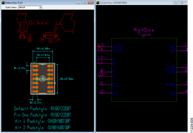
Figure 5. ADN4697E M-LVDS Transceiver Footprint and Symbol Window Using Ultra Librarian Reader.
- Select Mentor PADS (see Figure 1) and then select the v9 radio button.
- Click on the Export to Selected Tools option. A readme.txt file, similar to that shown in Figure 6, is then displayed. This provides guidance for importing the generated files into a Mentor PADS/Power Logic 4 or newer version.
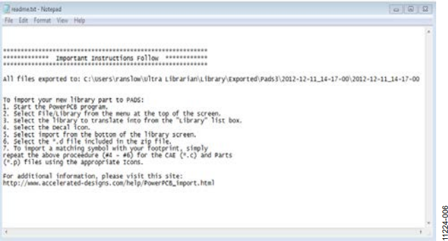
Figure 6. Exporting Files to Mentor PADS/Power Logic 4 or Newer Version and Importing to Mentor PADS v9.
Note that further instructions are provided by Accelerated Designs on the appropriate product page.
Once the instructions given in Figure 6 are followed, the part, part logic, and PCB decal are loaded into the Mentor PADS Library.
Figure 7 shows the component when added to a new schematic in the Mentor PADS v9 program. The PCB decal assignment information is noted in Figure 8.
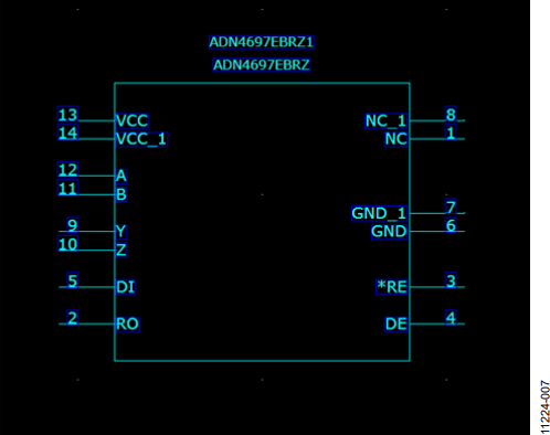
Figure 7. ADN4697E M-LVDS Transceiver Component Displayed in Mentor PADS v9.
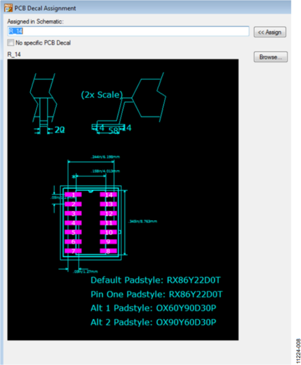
Figure 8. ADN4697E M-LVDS Transceiver Component PCB Decal Assignment Displayed in Mentor PADS v9.
Importing and Exporting the ADM3053 Isolated CAN Transceiver .BXL File
This example illustrates how to create a Cadence Allegro 15.2 or newer file from the ADM3053BRWZ.bxl file.
- Download the .bxl file from the ADM3053 symbols and footprints page and then wait for the file to download.
- Open the Ultra Librarian Binary Reader (see Figure 1).
- Select Load Data as shown in Figure 1.
- Navigate to the directory where you downloaded the ADM3053BRWZ.bxl file. This loads the tool with both a footprint and symbol window (see Figure 9).
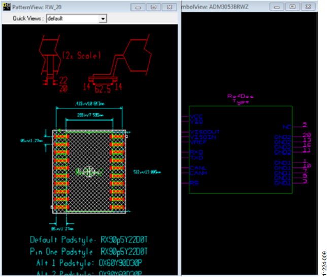
Figure 9. ADM3053 Isolated CAN Transceiver Footprint and Symbol Window Using Ultra Librarian Reader.
- Select the desired CAD tool from the listing provided in Figure 1. For this example, Cadence Allegro 15.2 or newer is selected.
- Select the Export to Selected Tools option. Export to Cadence 15.2 or newer, and follow the instructions provided to add the exported files to your Cadence library; the exported folder must be
- Copy the exported folder to the worklib folder for the Cadence project that you have created.
- Locate the ADM3053 symbol in your project library and add it to your schematic.
Note that further instructions are provided by Accelerated Designs on the appropriate product page.
Figure 10 shows the ADM3053 transceiver component added and displayed in Cadence Allegro.
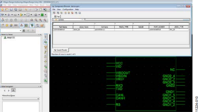
Figure 10. ADM3053 Isolated CAN Transceiver Component Added and Displayed in Cadence.
参考資料
More information on the Ultra Librarian Reader is available on the Accelerated Designs website.
