LTM4700
Info : RECOMMENDED FOR NEW DESIGNS
searchIcon
cartIcon

LTM4700

Dual 50A or Single 100A µModule Regulator with Digital Power System Management

Show More showmore-icon

Info : RECOMMENDED FOR NEW DESIGNS tooltip
Features
  • Dual 50A or Single 100A Digitally Adjustable Outputs with Digital Interface for Control, Compensation and Monitoring
  • Wide Input Voltage: 4.5V to 16V
  • Output Voltage Range: 0.5V to 1.8V
  • ~90% Full Load Efficiency from 12VIN to 1VOUT at 100A
  • ±0.5% Maximum DC Output Error Over Temperature
  • ±3% Current Readback Accuracy (25°C to 125°C)
  • Integrated Input Current Sense Amplifier
  • 400kHz PMBus-Compliant I2C Serial Interface
  • Supports Telemetry Polling Rates Up to 125Hz
  • Integrated 16-Bit ∆Σ ADC
  • Constant Frequency Current Mode Control
  • Parallel and Current Share Multiple Modules
  • 15mm × 22mm × 7.87mm BGA Package
  • Readable Data:
    • Input and Output Voltages, Currents, and Temperatures
    • Running Peak Values, Uptime, Faults and Warnings
    • Internal EEPROM and Fault Logging with ECC
  • Writable Data and Configurable Parameters:
    • Output Voltage, Voltage Sequencing and Margining
    • Digital Soft-Start/Stop Ramp
    • Optimize Analog Loop Compensation
    • OV/UV/OT, UVLO, Frequency and Phasing
Additional Details
show more Icon

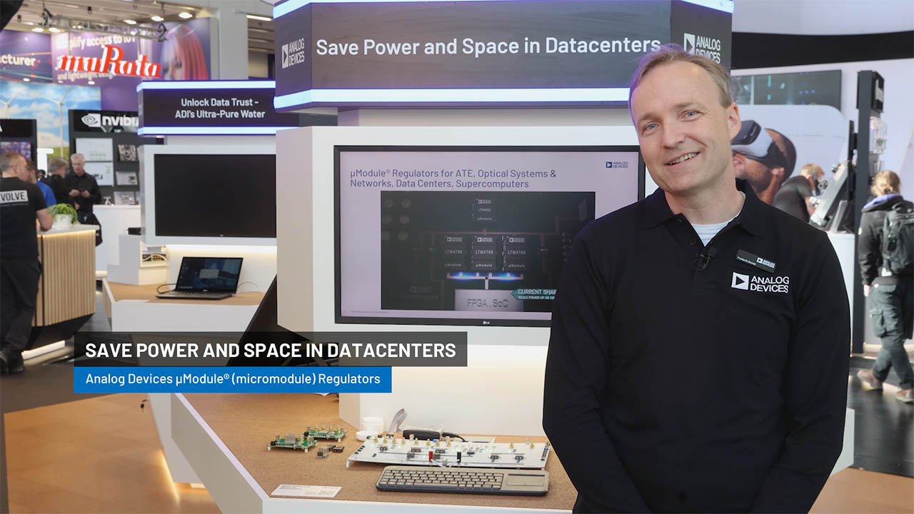
The LTM4700 is a dual 50A or single 100A step-down µModule® (power module) DC/DC regulator featuring remote configurability and telemetry-monitoring of power management parameters over PMBus— an open standard I2C-based digital interface protocol. The LTM4700 is comprised of fast analog control loops, precision mixed signal circuitry, EEPROM, power MOSFETs, inductors and supporting components. The LTM4700 product video is available on website.

The LTM4700’s 2-wire serial interface allows outputs to be margined, tuned and ramped up and down at programmable slew rates with sequencing delay times. Input and output currents and voltages, output power, temperatures, uptime and peak values are readable. Custom configuration of the EEPROM contents is not required. At start-up, output voltages, switching frequency, and channel phase angle assignments can be set by pin-strapping resistors. The LTpowerPlay® GUI and DC1613 USB-to-PMBus converter and demo kits are available.

The LTM4700 is offered in a 15mm × 22mm × 7.87mm BGA package available with SnPb or RoHS compliant terminal finish.

APPLICATIONS

  • System Optimization, Characterization and Data Mining in Prototype, Production and Field Environments
  • Telecom, Datacom, and Storage Systems

close icon

Documentation

Video

Part Model Pin/Package Drawing Documentation CAD Symbols, Footprints, and 3D Models
LTM4700EY#PBF
  • HTML
  • HTML
LTM4700IY
  • HTML
  • HTML
LTM4700IY#PBF
  • HTML
  • HTML

Filter by Model

reset

Reset Filters

Part Models

Product Lifecycle

PCN

Aug 5, 2024

- 24_0171

LTM4700 Internal Component Second Source

LTM4700EY#PBF

PRODUCTION

LTM4700IY

PRODUCTION

LTM4700IY#PBF

PRODUCTION

Nov 22, 2022

- 22_0262

Notification of Wafer Fab Location Change for 0.6µm BiCMOS Process

LTM4700EY#PBF

PRODUCTION

LTM4700IY

PRODUCTION

LTM4700IY#PBF

PRODUCTION

Sep 13, 2022

- 22_0193

Laser Top Mark Conversion for uModule COP and TMSV_COP Packages

LTM4700EY#PBF

PRODUCTION

LTM4700IY

PRODUCTION

LTM4700IY#PBF

PRODUCTION

Feb 28, 2020

- 20_0123

Micro-Module, Test Site Transfer from Analog Devices Singapore to Analog Devices Penang, Malaysia

LTM4700EY#PBF

PRODUCTION

LTM4700IY

PRODUCTION

LTM4700IY#PBF

PRODUCTION

Feb 5, 2020

- 20_0127

Supplier Material Change for µModule

LTM4700EY#PBF

PRODUCTION

LTM4700IY

PRODUCTION

LTM4700IY#PBF

PRODUCTION

Filter by Model

reset

Reset Filters

Part Models

Product Lifecycle

PCN

Aug 5, 2024

- 24_0171

arrow down

LTM4700 Internal Component Second Source

LTM4700EY#PBF

PRODUCTION

LTM4700IY

PRODUCTION

LTM4700IY#PBF

PRODUCTION

Nov 22, 2022

- 22_0262

arrow down

Notification of Wafer Fab Location Change for 0.6µm BiCMOS Process

LTM4700EY#PBF

PRODUCTION

LTM4700IY

PRODUCTION

LTM4700IY#PBF

PRODUCTION

Sep 13, 2022

- 22_0193

arrow down

Laser Top Mark Conversion for uModule COP and TMSV_COP Packages

LTM4700EY#PBF

PRODUCTION

LTM4700IY

PRODUCTION

LTM4700IY#PBF

PRODUCTION

Feb 28, 2020

- 20_0123

arrow down

Micro-Module, Test Site Transfer from Analog Devices Singapore to Analog Devices Penang, Malaysia

LTM4700EY#PBF

PRODUCTION

LTM4700IY

PRODUCTION

LTM4700IY#PBF

PRODUCTION

Feb 5, 2020

- 20_0127

arrow down

Supplier Material Change for µModule

LTM4700EY#PBF

PRODUCTION

LTM4700IY

PRODUCTION

LTM4700IY#PBF

PRODUCTION

Evaluation Kits 10

reference details image

DC2702A-B

OBSOLETE: LTM4700 Demo Board | Dual 50A or Single 100A μModule Regulator with Digital Power System Management

zoom

DC2702A-B

OBSOLETE: LTM4700 Demo Board | Dual 50A or Single 100A μModule Regulator with Digital Power System Management

OBSOLETE: LTM4700 Demo Board | Dual 50A or Single 100A μModule Regulator with Digital Power System Management

Product Detail

This evaluation board is obsolete and no longer recommended. The replacement board is the DC2702B-B.

Demonstration circuit 2702A-B is a single output, dual phases, high efficiency, high density, µModule regulator with 4.5V to 16V input range. The output voltage is adjustable from 0.5V to 1.8V and it can supply 100A maximum load current. The demo board has a LTM4700 µModule regulator, which is a dual 50A or single 100A step-down regulator with digital power system management. Please see LTM4700 data sheet for more detailed information.

DC2702A-B powers up to default settings and produces power based on configuration resistors without the need for any serial bus communication. This allows easy evaluation of the DC/DC converter. To fully explore the extensive the GUI software LTpowerPlay® onto your PC and use LTC’s I2C/SMBus/PMBus dongle DC1613A to connect to the board. LTpowerPlay allows the user to reconfigure the part on-the-fly and store the configuration in EEPROM, view telemetry of voltage, current, temperature and fault status.

reference details image

DC2784A-B

OBSOLETE: LTM4700 High Current, PolyPhase Step-Down Power µModule Supply with Digital Power System Management 3×LTM4700, 300A

zoom

DC2784A-B

OBSOLETE: LTM4700 High Current, PolyPhase Step-Down Power µModule Supply with Digital Power System Management 3×LTM4700, 300A

OBSOLETE: LTM4700 High Current, PolyPhase Step-Down Power µModule Supply with Digital Power System Management 3×LTM4700, 300A

Product Detail

This evaluation board is obsolete and no longer recommended. The replacement board is the DC2784B-B (coming soon).

Demonstration circuit 2784A-B is a high efficiency, high density, µModule regulator with 4.5V to 16V input range. The output voltage is adjustable from 0.5V to 1.8V and it can supply 300A maximum load current. The demo board has three LTM4700 µModule regulators, which is a dual 50A or single 100A step-down regulator with digital power system management. Please see LTM4700 data sheet for more detailed information.

DC2784A-B powers up to default settings and produces power based on configuration resistors without the need for any serial bus communication. This allows easy evaluation of the DC/DC converter. To fully explore the extensive power system management features of the part, download the GUI software LTpowerPlay® onto your PC and use ADI’s I2C/SMBus/PMBus dongle DC1613A to connect to the board. LTpowerPlay allows the user to reconfigure the part on the fly and store the configuration in EEPROM, view telemetry of voltage, current, temperature and fault status.

reference details image

DC2784A-C

LTM4700 High Current, PolyPhase Step-Down Power µModule Supply with Digital Power System Management 4×LTM4700, 400A

zoom

DC2784A-C

LTM4700 High Current, PolyPhase Step-Down Power µModule Supply with Digital Power System Management 4×LTM4700, 400A

LTM4700 High Current, PolyPhase Step-Down Power µModule Supply with Digital Power System Management 4×LTM4700, 400A

Product Detail

Demonstration circuit 2784A-C is a high efficiency, high density, µModule regulator with 4.5V to 16V input range. The output voltage is adjustable from 0.5V to 1.8V and it can supply 400A maximum load current. The demo board has four LTM4700 µModule regulators, which is a dual 50A or single 100A step-down regulator with digital power system management. Please see LTM4700 data sheet for more detailed information.

DC2784A-C powers up to default settings and produces power based on configuration resistors without the need for any serial bus communication. This allows easy evaluation of the DC/DC converter. To fully explore the extensive power system management features of the part, download the GUI software LTpowerPlay® onto your PC and use ADI’s I2C/SMBus/PMBus dongle DC1613A to connect to the board. LTpowerPlay allows the user to reconfigure the part on the fly and store the configuration in EEPROM, view telemetry of voltage, current, temperature and fault status.

reference details image

DC2784A-A

OBSOLETE: LTM4700 High Current, PolyPhase Step-Down Power µModule Supply with Digital Power System Management 2×LTM4700, 200A

zoom

DC2784A-A

OBSOLETE: LTM4700 High Current, PolyPhase Step-Down Power µModule Supply with Digital Power System Management 2×LTM4700, 200A

OBSOLETE: LTM4700 High Current, PolyPhase Step-Down Power µModule Supply with Digital Power System Management 2×LTM4700, 200A

Product Detail

This evaluation board is obsolete and no longer recommended. The replacement board is the DC2784B-A (coming soon).

Demonstration circuit 2784A-A is a high efficiency, high density, µModule regulator with 4.5V to 16V input range. The output voltage is adjustable from 0.5V to 1.8V and it can supply 200A maximum load current. The demo board has two LTM4700 µModule regulators, which is a dual 50A or single 100A step-down regulator with digital power system management. Please see LTM4700 data sheet for more detailed information.

DC2784A-A powers up to default settings and produces power based on configuration resistors without the need for any serial bus communication. This allows easy evaluation of the DC/DC converter. To fully explore the extensive power system management features of the part, download the GUI software LTpowerPlay® onto your PC and use ADI’s I2C/SMBus/PMBus dongle DC1613A to connect to the board. LTpowerPlay allows the user to reconfigure the part on the fly and store the configuration in EEPROM, view telemetry of voltage, current, temperature and fault status.

reference details image

DC2702A-A

OBSOLETE: LTM4700EY Dual 50A or Single 100A µModule Regulator With Digital Power System Management

zoom

DC2702A-A

OBSOLETE: LTM4700EY Dual 50A or Single 100A µModule Regulator With Digital Power System Management

OBSOLETE: LTM4700EY Dual 50A or Single 100A µModule Regulator With Digital Power System Management

Product Detail

This evaluation board is obsolete and no longer recommended. The replacement board is the DC2702B-A.

Demonstration circuit 2702A-A is a dual-output, high efficiency, high density, µModule® regulator with 4.5V to 16V input range. Each output can supply 50A maximum load current. The demo board has a LTM4700 µModule regulator, which is a dual 50A or single 100A step-down regulator with digital power system management. Please see LTM4700 data sheet for more detailed information.

DC2702A-A powers up to default settings and produce power based on configuration resistors without the need for any serial bus communication. This allows easy evaluation of the DC/DC converter. To fully explore the extensive power system management features of the part, download the GUI software LTpowerPlay® onto your PC and use ADI’s I2C/SMBus/PMBus dongle DC1613A to connect to the board. LTpowerPlay allows the user to reconfigure the part on-the-fly and store the configuration in EEPROM, view telemetry of voltage, current, temperature and fault status.

reference details image

DC2702B-B

LTM4700 | Single 100A μModule Regulator with Digital Power System Management

zoom

DC2702B-B

LTM4700 | Single 100A μModule Regulator with Digital Power System Management

LTM4700 | Single 100A μModule Regulator with Digital Power System Management

Product Detail

Demonstration circuit 2702B-B is a single output, dual-phase, high efficiency, high density, μModule® regulator with a 4.5V to 16V input range. The output voltage is adjustable from 0.5V to 1.8V and can supply 100A maximum load current. The DC2702B-B demo board has a LTM4700 μModule regulator, a dual 50A or single 100A step-down regulator with digital power system management. Refer to the LTM4700 data sheet for more detailed information.

DC2702B-B powers up to default settings and produces power based on configuration resistors without serial bus communication. This feature allows easy evaluation of the DC/DC converter. To fully explore the extensive power system management features of the LTM4700, download the GUI software LTpowerPlay® onto your PC and use Analog Devices I2C/SMBus/PMBus dongle DC1613A to connect to the board. LTpowerPlay allows the user to reconfigure the part on-the-fly, store the configuration in EEPROM, view telemetry of voltage, current, temperature and fault status.

reference details image

DC2702B-A

LTM4700EY | Dual 50A or Single 100A μModule Regulator with Digital Power System Management

zoom

DC2702B-A

LTM4700EY | Dual 50A or Single 100A μModule Regulator with Digital Power System Management

LTM4700EY | Dual 50A or Single 100A μModule Regulator with Digital Power System Management

Product Detail

Demonstration circuit 2702B-A is a dual-output, high efficiency, high density, μModule® regulator with 4.5V to 16V input range. Each output can supply 50A maximum load current. The demo board has a LTM4700 μModule regulator, which is a dual 50A or single 100A step-down regulator with digital power system management. See the LTM4700 data sheet for more information.

The DC2702B-A powers up to default settings and produces power based on configuration resistors without the need for any serial bus communication. This allows easy evaluation of the DC/DC converter. To fully explore the extensive power system management features of the part, download the GUI software LTpowerPlay® to a PC and use ADI’s I2C/SMBus/PMBus dongle DC1613A to connect to the board. LTpowerPlay allows for on-the-fly reconfiguration of the part, stores the configuration in EEPROM, and enables viewing of voltage, current, temperature, and fault status telemetry.

reference details image

DC2784B-A

LTM4700 | High Current, PolyPhase® Step-Down Power μModule Supply with Digital Power System Management 2 × LTM4700, 200A

zoom

DC2784B-A

LTM4700 | High Current, PolyPhase® Step-Down Power μModule Supply with Digital Power System Management 2 × LTM4700, 200A

LTM4700 | High Current, PolyPhase® Step-Down Power μModule Supply with Digital Power System Management 2 × LTM4700, 200A

Product Detail

Demonstration circuit 2784B-A is a high efficiency, high density, μModule® regulator with 4.5V to 16V input range. The output voltage is adjustable from 0.5V to 1.8V and it can supply 200A maximum load current. The demo board has two LTM®4700 μModule regulators, which is a dual 50A or single 100A step-down regulator with digital power system management. See LTM4700 data sheet for more detailed information.

The DC2784B-A powers up to default settings and produces power based on configuration resistors without the need for any serial bus communication. This allows easy evaluation of the DC/DC converter. To fully explore the extensive power system management features of the part, download the graphical user interface (GUI) software LTpowerPlay® onto your PC and use Analog Devices I2C/SMBus/PMBus dongle DC1613A to connect to the board. The LTpowerPlay allows the user to reconfigure the part on-the-fly and store the configuration in EEPROM, view telemetry of voltage, current, temperature, and fault status.

GUI Download

The software can be downloaded from LTpowerPlay.

For more details and instructions of LTpowerPlay, please refer to LTpowerPlay GUI for LTM4700 Quick Start Guide.

Design files for this circuit board are available.

reference details image

DC2784B-C

LTM4700 | High Current, PolyPhase® Step-Down Power μModule Supply with Digital Power System Management 4 × LTM4700, 400A

zoom

DC2784B-C

LTM4700 | High Current, PolyPhase® Step-Down Power μModule Supply with Digital Power System Management 4 × LTM4700, 400A

LTM4700 | High Current, PolyPhase® Step-Down Power μModule Supply with Digital Power System Management 4 × LTM4700, 400A

Product Detail

Demonstration circuit 2784B-C is a high-efficiency, high-density, μModule® regulator with a 4.5V to 16V input range. The output voltage is adjustable from 0.5V to 1.8V, and it can supply 400A maximum load current. The demo board has four LTM®4700 μModule regulators, which is a dual 50A or single 100A step-down regulator with digital power system management. See the LTM4700 data sheet for more detailed information.

The DC2784B-C powers up to default settings and produces power based on configuration resistors without the need for any serial bus communication. This allows easy evaluation of the DC/DC converter. To fully explore the extensive power system management features of the All registered trademarks and trademarks are the property of their respective owners. part, download the GUI software LTpowerPlay® onto a PC and use ADI’s I2C/SMBus/PMBus dongle DC1613A to connect to the board. LTpowerPlay allows on-the-fly reconfiguration of the part and stores the configuration in EEPROM, view telemetry of voltage, current, temperature and fault status.

GUI Download

Download software from LTpowerPlay.

For more details and instructions of LTpowerPlay, refer to LTpowerPlay GUI for LTM4700 Quick Start Guide.

Design files for this circuit board are available.

reference details image

DC2784B-B

High Current, PolyPhase® Step-Down Power μModule Supply with Digital Power System Management 3 × LTM4700, 300A

zoom

DC2784B-B

High Current, PolyPhase® Step-Down Power μModule Supply with Digital Power System Management 3 × LTM4700, 300A

High Current, PolyPhase® Step-Down Power μModule Supply with Digital Power System Management 3 × LTM4700, 300A

Product Detail

Demonstration circuit 2784B-B is a high efficiency, high density, μModule® regulator with 4.5V to 16V input range. The output voltage is adjustable from 0.5V to 1.8V and it can supply 300A maximum load current. The demo board has three LTM®4700 μModule regulators, which is a dual 50A or single 100A step-down regulator with digital power system management. Please see LTM4700 data sheet for more detailed information.

DC2784B-B powers up to default settings and produces power based on configuration resistors without the need for any serial bus communication. This allows easy evaluation of the DC/DC converter. To fully explore the extensive power system management features of the part, download All registered trademarks and trademarks are the property of their respective owners. the GUI software LTpowerPlay® onto your PC and use ADI’s I2C/SMBus/PMBus dongle DC1613A to connect to the board. LTpowerPlay allows the user to reconfigure the part on-the-fly and store the configuration in EEPROM, view telemetry of voltage, current, temperature and fault status.

GUI Download

The software can be downloaded from LTpowerPlay.

For more details and instructions of LTpowerPlay, please refer to LTpowerPlay GUI for LTM4700 Quick Start Guide.

Tools & Simulations 2

LTspice® is a powerful, fast and free simulation software, schematic capture and waveform viewer with enhancements and models for improving the simulation of analog circuits.

To launch ready-to-run LTspice demonstration circuits for this part:

Step 1: Download and install LTspice on your computer.

Step 2: Click on the link in the section below to download a demonstration circuit.

Step 3: If LTspice does not automatically open after clicking the link below, you can instead run the simulation by right clicking on the link and selecting “Save Target As.” After saving the file to your computer, start LTspice and open the demonstration circuit by selecting ‘Open’ from the ‘File’ menu.

Reference Designs 5

Xilinx VU37P Board

zoomopens a dialog

HTG-937: Xilinx Virtex UltraScale+ ™ VU37P/VU47P HBM Development Board

Features and Benefits

The HTG-937 provides access to large FPGA gate density and 8GB/16GB of high bandwidth memory. It is populated with the Xilinx Zynq Virtex Ultrascale VU37P, or VU47P. Analog Devices power solution on this platform is fully validated to meet the requirements of Xilinx Zynq Virtex Ultrascale FPGAs to ensure a robust power delivery solution.

DC/DC μModule regulators are used on the HTG-937 to power Xilinx FPGA and/or SoC rails as well as other system rails. These regulators are highly integrated solutions with built in controller, power FETs, inductors, and capacitors that simplify layout and provide robust power delivery performance.

We provide supporting documentation including power schematics, layout, LTpowerPlanner and applicable LTpowerPlay configuration files to enable you to validate the power solution for your application seamlessly.

View Detailed Reference Design external link
HTG-AI & Prime PCIe Express Platform - Top View

Versal PRIME /AI PCI Express Platform

zoomopens a dialog

HTG-VSL1

Versal PRIME /AI PCI Express Platform

HTG-VSL1

Circuits from the lab

tooltip Info:Circuits from the lab
Versal PRIME /AI PCI Express Platform

Features and Benefits

  • Xilinx Versal AI Core and Prime series solves a broad range of industry-specific problems with performance and flexibility. Core use cases  include storage acceleration,  data center network acceleration, 5G xHaul and Passive optical networks.

  • The HTG-VSL1 AI Core and Prime PCIe express platform allows easy and versatile functional expansion through two Vita 57.4 compliant High-Pin-Count  FMC+ ports and one high-speed AcceleRate® port.

  • Analog Devices, Inc. supports power delivery solutions for the HTG-VSL1 for the Versal AI Core and Versal Prime PCIe express platform. DC/DC μModule regulators are used on the HTG-VSL1 to power Xilinx FPGA and/or SoC rails as well as other system rails. These regulators are highly integrated solutions with built in controller, power FETs, inductors, and capacitors that simplify layout and provide robust power delivery performance.

  • ADI provides supporting documentation including power schematics, layout, LTpowerPlanner® and applicable LTpowerPlay® configuration files to enable you to validate the power solution for your application seamlessly.

  • For a complete list power designs and use cases, please contact your local FAE.

  • Key Power DC DC Modules include:
    • LTM4700 is a Dual 50A or Single 100A μModule Regulator with Digital Power System Management, PMBus
    • LTM4638 is a 15A Step-Down DC/DC μModule Regulator
    • LTM4625 is a 5A Step-Down DC/DC μModule Regulator
    • LTM4632 is a Triple Output, Step-Down μModule Regulator for DDR-QDR4 Memory
    • LTC2937 is a Programmable Six Channel Sequencer and Voltage Supervisor with EEPROM
View Detailed Reference Design external link
agilex7 alternative umodule

Altera FPGA

zoomopens a dialog

Intel Agilex 7 FPGA F-series Development Kit (Alternative µModule)

Altera FPGA

Intel Agilex 7 FPGA F-series Development Kit (Alternative µModule)

Circuits from the lab

tooltip Info:Circuits from the lab
Altera FPGA

Features and Benefits

  • Intel Agilex 7 F-Series devices target a wide range of applications across many markets. This series offers transceiver rates up to 58 Gbps, advanced DSP blocks supporting multiple precisions of fixed-point and floating-point operations, and high-performance crypto blocks.
  • Analog Devices has worked closely with FPGA and processor manufacturers to develop verified power solutions that optimize cost, size and efficiency in high performance applications.
  • Our reference designs are supported by an intuitive design tool set and IP.
  • ADI provides supporting documentation including LTpowerPlanner and applicable LTpowerPlay configuration files to enable you to validate the power solution for your application seamlessly. Our team can provide samples and/or evaluation boards for quick validation that can speed time to market in the most complex applications.
  • For a complete list power designs and use cases, please contact your local FAE.
View Detailed Reference Design external link
Stratix 10 GX PCIE FPGA Development Kit

zoomopens a dialog

Intel Stratix 10 FPGA PCIe Development Kit

Intel Stratix 10 FPGA PCIe Development Kit

Circuits from the lab

tooltip Info:Circuits from the lab

Features and Benefits

  • Analog Devices has worked closely with Intel PSG to develop verified power solutions that optimize cost, size and efficiency in high performance applications.
  • The validated power solutions include uModules power products that address time and space constraints while delivering high efficiency, reliability, and low noise.
  • The actual power tree represents the best solution at time of design.
  • A recommended power tree has also been included to present the ideal solution at time of Stratix 10 GX PCIe development kit release. An updated alternate version of the power tree represents the latest solutions available from Analog Devices. For many applications, an intermediate rail is not ideal, so recommendations an alternate power tree that allow for direct power conversion from 12V input is provided below.
View Detailed Reference Design external link
Stratix 10 GX Signal Integrity Development Kit

zoomopens a dialog

Stratix 10 GX Signal Integrity Development Kit

Stratix 10 GX Signal Integrity Development Kit

Circuits from the lab

tooltip Info:Circuits from the lab

Features and Benefits

  • Analog Devices has worked closely with Intel PSG to develop verified power solutions that optimize cost, size and efficiency in high performance applications.
  • The validated power solutions include uModules power products that address time and space constraints while delivering high efficiency, reliability, and low noise.
  • The actual power tree represents the best solution at time of design.
  • A recommended power tree has also been included to present the ideal solution at time of Stratix 10 GX SI development kit release. An updated alternate version of the power tree represents the latest solutions available from Analog Devices. For many applications, an intermediate rail is not ideal, so recommendations for an alternate power tree that allows for direct power conversion from 12V input is provided below.
View Detailed Reference Design external link

Recently Viewed