MAX32660

新規設計に推奨

小型、超低電力、FPU内蔵Arm Cortex-M4プロセッサベースのマイクロコントローラ(MCU)、256KBのフラッシュおよび96KBのSRAM内蔵

DARWIN Generation U MCUは電力と性能に関心のあるエンジニアに最適です

製品モデル
11
1Ku当たりの価格
最低価格:$1.29
利用上の注意

アナログ・デバイセズ社は、提供する情報が正確で信頼できるものであることを期していますが、その情報の利用に関して、あるいはその利用によって生じる第三者の特許やその他の権利の侵害に関して一切の責任を負いません。また、アナログ・デバイセズ社の特許または特許の権利の使用を明示的または暗示的に許諾するものでもありません。仕様は予告なしに変更する場合があります。本紙記載の商標および登録商標は、各社の所有に属します。


本データシートの英語以外の言語への翻訳はユーザの便宜のために提供されるものであり、リビジョンが古い場合があります。最新の内容については、必ず最新の英語版をご参照ください。

なお、日本語版のデータシートは基本的に「Rev.0」(リビジョン0)で作成されています。そのため、英語版が後に改訂され、複数製品のデータシートがひとつに統一された場合、同じ「Rev.0」の日本語版のデータシートが異なる製品のデータシートとして表示されることがあります。たとえば、「ADM3307E」の場合、日本語データシートをクリックすると「ADM3311E」が表示されます。これは、英語版のデータシートが複数の製品で共有できるように1本化され、「ADM3307E/ADM3310E/ADM3311E/ADM3312E/ADM3315E」(Rev.G)と改訂されたからで、決して誤ってリンクが張られているわけではありません。和文化されたデータシートを少しでも有効に活用していただくためにこのような方法をとっておりますので、ご了解ください。

Viewing:

製品の詳細

  • ウェアラブル機器用高効率マイクロコントローラ
    • 内部発振器:最大96MHzまで動作
    • フラッシュメモリ:256KB
    • SRAM:96KB (最低電力バックアップモードでの保持オプション)
    • 命令キャッシュ:16KB
    • メモリ保護ユニット(MPU)
    • 低いVCORE電源電圧:1.1V
    • GPIO動作範囲:3.6V
    • 内部LDOによって単一電源での動作を提供
    • 広い動作温度:-40℃~+105℃
  • 電源管理によってバッテリアプリケーションのアップタイムを最大化
    • アクティブ電流:85µA/MHz (フラッシュからの実行時)
    • バックアップモードでの全メモリ保持電力:2µA (VDD = 1.8V)
    • 超低電力RTC:450nA (VDD = 1.8V)
    • 内部リング発振器:80kHz
  • 最適なペリフェラルミックスによってプラットフォーム拡張性を提供
    • 最大14の汎用入出力端子
    • 最大2つのSPIマスター/スレーブ
    • I2Sマスター/スレーブ
    • 最大2つのUART
    • 最大2つのI2Cマスター/スレーブ、3.4Mbpsハイスピード
    • 4チャネル標準DMAコントローラ
    • 3つの32ビットタイマー
    • ウォッチドッグタイマ
    • CMOSレベルRTC出力:32.768kHz
MAX32660
小型、超低電力、FPU内蔵Arm Cortex-M4プロセッサベースのマイクロコントローラ(MCU)、256KBのフラッシュおよび96KBのSRAM内蔵
世界最小Arm® Cortex®-M4Fマイクロコントローラ(MCU)
myAnalogに追加

myAnalogの製品セクション(通知受け取り)、既存/新規プロジェクトに製品を追加する。

新規プロジェクトを作成
質問する
サポート

アナログ・デバイセズのサポート・ページはアナログ・デバイセズへのあらゆるご質問にお答えするワンストップ・ポータルです。


ドキュメント

さらに詳しく
myAnalogに追加

myAnalogの製品セクション(通知受け取り)、既存/新規プロジェクトに製品を追加する。

新規プロジェクトを作成

ソフトウェア・リソース

デバイス・ドライバ 1


ツールおよびシミュレーション


評価用キット

eval board
MAX32660-EVSYS

MAX32660の評価キット

機能と利点

  • MAX32660マイクロコントローラ
    • Arm Cortex-M4F:96MHz
    • フラッシュメモリ:256KB
    • SRAM:96KB
    • 命令キャッシュ:16KB
    • 2つのSPI
    • 2つのI2C
    • 2つのUART
    • 14のGPIO
  • DIPブレークアウトボード
    • 100milピッチデュアルインラインピンヘッダ
    • ブレッドボード対応
  • 内蔵ペリフェラル
    • 赤インジケータLED
    • ユーザープッシュボタン
  • MAX32625PICOベースのデバッグアダプタ
    • CMSIS-DAP SWDデバッガ
    • 仮想UARTコンソール

製品詳細

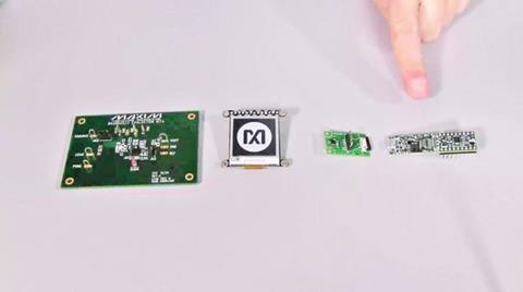
MAX32660の評価システムは、MAX32660の全機能へのアクセスを提供する小型の開発プラットフォームを、小型の使いやすいボードで提供します。MAX32625PICOベースのデバッグアダプタがメインボードに接続されています。このアダプタは、プログラミング完了後に取り外すことができます。デバッグモジュールは、オプションのDAPLink機能用10ピンArm® Cortex®デバッグコネクタに対応しています。組み合わせたサイズは0.65インチ × 2.2インチで、メインボード単体のサイズは0.65インチ × 0.95インチです。外部接続は、スルーホールおよびSMTアプリケーションの両方に対応する2列ヘッダ実装で終端処理されています。このボードは、各種のアプリケーションに容易に内蔵可能な非常に小型のスペースで、強力な処理サブシステムを提供します。

アプリケーション

  • フィットネスモニタ
  • 産業用センサー
  • IoT
  • 光モジュール:QSFP-DD、QSFP、400G
  • ポータブル医療機器
  • スポーツウォッチ
  • ウェアラブル医療パッチ

eval board
MAXNANOPWRBD

MAX32660、MAX11615、MAX40018、MAX9119、MAX9634、MAX17222の評価キット

機能と利点

  • 超低電力MAX32660 Arm Cortex M4F
  • MAX11615低電力8チャネル12ビットADC
  • MAX40007ナノパワーオペアンプ
  • MAX9119ナノパワーコンパレータ
  • MAX9634電流検出アンプ
  • MAX17222ブーストコンバータ
  • PCBに実装されたボタン電池電源

製品詳細

MAXNANOPWRBD評価キットは、マキシムのナノパワー技術と、超低電力、低ピン数、FPU内蔵Arm® Cortex®-M4プロセッサのMAX32660を組み合わせて、1つの1.5Vアルカリボタン電池で動作する簡素なデジタルマルチメーターのアプリケーション例を作ります。

このキットには、以下のアイテムが含まれています。

  • MAXNANOPWRBD#回路基板
  • MAX326325PICO JTAGデバッガ/プログラマ

アプリケーション

  • フィットネスモニタ
  • 産業用センサー
  • IoT
  • 光モジュール:QSFP-DD、QSFP、400G
  • ポータブル医療機器
  • スポーツウォッチ
  • ウェアラブル医療パッチ

MAX32660-EVSYS
MAX32660の評価キット
MAX32660-EVSYS:ボード写真
MAXNANOPWRBD
MAX32660、MAX11615、MAX40018、MAX9119、MAX9634、MAX17222の評価キット
MAXNANOPWRBD:ボード写真

リファレンス・デザイン

MAXREFDES9001: Secured IoT LoRa Sensor Nodes using the DS28S60 and Google Cloud
MAXREFDES9001 Circuits from the Lab®

Secured IoT LoRa Sensor Nodes using the DS28S60 and Amazon Web Services (AWS)

機能と利点

  • DS28S60 ChipDNA technology protects private and secret keys against invasive attacks.
  • DS28S60 provides end-to-end security using hardware-based ECDSA authentication, ECDH key exchange, and AES-GCM authenticated encryption.
  • Complete low-power sensor node board design
  • Sample LoRaWAN gateway implementation based on Raspberry Pi
  • Sample cloud application implemented in AWS infrastructure highlighting end-to-end security with the sensor board’s DS28S60 including ECDH key exchange, and AES-GCM secure communication.
  • Source code
  • Peripheral module-compatible sensor expansion port
  • Raspberry Pi enables portable LoRaWAN gateway deployment.
MAXREFDES9002
MAXREFDES9002 Circuits from the Lab®

C-source Reference for Operating the DS28E18 from Cortex-M4 GPIO Pins

機能と利点

Features

  • Power and communication to I2C and SPI sensors through two wires
  • 512-byte command sequencer for autonomous operation
  • Up to 10mA at 3.3V sensor power derived from 1-Wire
  • Up to 100m distance with the 1-Wire interface
  • Example C-code demonstrates how to interface to I2C and SPI sensors
maxrefdes300 figure 1
MAXREFDES300 Circuits from the Lab®

RFID Datalogger for Healthcare and Cold-Chain Logistics

機能と利点

Maxim’s MAX32660 Microcontroller

  • Ultra-Low-Power Operation
  • 256KB Flash Memory and 96KB SRAM
  • 3.05mm (L) x 3.05mm (W) x 0.80mm (H) TQFN Package

Axzon’s RFM405 Wireless Passive Sensor

  • On-Chip Temperature Sensor
  • UHF/RAIN Operation – EPCglobal® Gen2 Compliant
maxrefdes9004 board
MAXREFDES9004 Circuits from the Lab®

C-source Reference for Operating the DS2485 Combined with a DS28E18 from a Cortex-M4 Microcontroller

機能と利点

  • Dedicated 1-Wire Master for Convenient 1-Wire Processing
  • Up to 100m Remote Communication with Connected 1-Wire Slave Devices
  • C-Code Demonstrates How to Use the DS2485 in Software Including an Example with the DS28E18

Designed–Built–Tested

A simple, cost-efficient, 1-Wire master is demonstrated using the DS2485 for a simple sensor application using the MAX32660 host microcontroller. This reference design includes the following major components: one each of MAX32660 Cortex-M4 microcontroller, DS2485 1-Wire master, DS28E18 1-Wire to I2C/SPI bridge and an I2C temperature sensor module. This document describes the hardware shown above as well as its supplementing software. It provides a detailed, systematic technical guide to set up and understand the MAXREFDES9004 reference design. The system has been built and tested, details of which follow later in this document.

maxrefdes9007 board
MAXREFDES9007 Circuits from the Lab®

Arm Cortex-M4 I/O Implemented 1-Wire Secure Authenticator Demo and Real Time Measurements

機能と利点

  • ECC-256 Compute Engine
  • FIPS 186 ECDSA P256 Signature and Verification
  • ECDH Key Exchange with Authentication Prevents Man-in-the-Middle Attacks
  • ECDSA Authenticated R/W of Configurable Memory
  • SHA-256 Compute Engine
  • FIPS 180 MAC for Secure Download/Boot Operations
  • FIPS 198 HMAC for Bidirectional Authentication and Optional GPIO Control
  • Two GPIO Pins with Optional Authentication Control
  • Open-Drain, 4mA/0.4V
  • Optional SHA-256 or ECDSA Authenticated On/Off and State Read
  • Optional Set On/Off After Multiblock Hash for Secure Boot/Download
  • RNG with NIST SP 800-90B Compliant Entropy Source with Function to Read Out
  • Optional Chip-Generated Pr/Pu Key Pairs for ECC Operations
  • 17-Bit One-Time Settable, Nonvolatile Decrement-Only Counter with Authenticated Read
  • 8Kbits of EEPROM for User Data, Keys, and Certificates
  • Unique and Unalterable Factory Programmed 64-Bit Identification Number (ROM ID)
  • Optional Input Data Component to Crypto and Key Operations
  • Single-Contact 1-Wire Interface Communication with Host at 11.7kbps and 62.5kbps
  • Operating Range: 3.3V ±10%, -40°C to +85°C
  • 6-Pin TDFN-EP Package (3mm x 3mm)
  • Accessory and Peripheral Secure Authentication
  • IoT Node Crypto-Protection
  • Secure Boot or Download of Firmware and/or System Parameters
  • Secure Storage of Cryptographic Keys for a Host Controller

Application

  • IoT Node Crypto-Protection
  • Accessory and Peripheral Secure Authentication
  • Secure Storage of Cryptographic Keys for a Host Controller
  • Secure Boot or Download of Firmware and/or System Parameters
MAXREFDES1207 Block Diagram
MAXREFDES1207 Circuits from the Lab®

Heart-Rate Monitor Wrist Band Using the MAX77651B

機能と利点

Description

The MAXREFDES1207 is a reference design for wearable application based on a total Analog Devices solution which includes the MAX32660, MAX30112, MAX77651B, and MAX40005. This solution demonstrates how a small size, low cost, low power, high accuracy heart-rate (HR) monitor can be easily implemented. This design can monitor heart rate using two green LEDs.

The MAX30112 is an optimized pulse-oximeter and heartrate AFE for wearable health. It has a high-resolution, optical readout signal-processing channel with built-in ambient light cancellation as well as high-current LED driver DACs to form a complete optical readout signal chain. With external LED(s) and photodiode(s), the MAX30112 offers the lowest power, highest performance heart-rate detection solution for wrist applications. The MAX77651B provides highly-integrated battery charging and power supply solutions for low-power wearable applications where size and efficiency are critical. The device features a SIMO buckboost regulator that provides three independently programmable power rails from a single inductor to minimize total solution size. A highly configurable linear charger supports a wide range of Li+ battery capacities and includes battery temperature monitoring for additional safety (JEITA). The MAX32660 is an ultra-low-power, cost-effective, highly- integrated microcontroller unit (MCU) designed for battery- powered devices and wireless sensors. It combines a flexible and versatile power management unit with the powerful Arm® Cortex®-M4 with floating point unit (FPU). The MAX40005 is a tiny, single comparator which is ideal for a wide variety of portable electronics applications such as cell phones, media players, and notebooks that have extremely tight board space and power constraints. The design also contains an FTDI FT234 USB-to-serial UART interface.

EVAL CN0583 CRR1 ANGLE web
CN0583 Circuits from the Lab®

Multistandard Micropower Verified Smoke Detection System-on-Module

機能と利点

The CN0583 reference design plus related software is designed and tested to meet UL 217 8th edition, EN14604:2005, and similar smoke/fire detection standards. To address the needs of different customers, a number of solution offerings are available which are summarized in the table below. ​

The hardware is designed to accelerate prototyping and the evaluation of the embedded smoke detection algorithm. The hardware is comprised of the EVAL-CN0583-SOM and EVAL-CN0583-CRR1 Carrier Board.​

The Data package (ADSW-SMOKEDATA-PRODLIC) provides an extensive (1000+) smoke dataset taken at UL 217 and EN14604 certified facilities for those who wish to develop their own algorithm. It includes the CN0583 source code for initialization, calibration, environmental compensation, data pre-processing - but excludes the detection algorithm.​

The Algorithm package (ADSW-SMOKEDATA-PRODLIC) includes everything in the Data package and adds UL & EN validated smoke detection algorithm and associated algorithm project files.

  • Complete Smoke Detector System on Module
  • Micropower Operation for >10 Year Battery Lifetime
  • UL 217 & UL 268 Verified Smoke Detector Algorithm
  • EN 54-7 & EN 14604 Verified Smoke Detector Algorithm
MAXREFDES164
IO-Link Local Temperature Sensor
MAXREFDES164
MAXREFDES164
MAXREFDES164
MAXREFDES1261
Asset Tracker Power Management Platform
maxrefdes1261 board
MAXREFDES9001
Secured IoT LoRa Sensor Nodes using the DS28S60 and Amazon Web Services (AWS)
MAXREFDES9001: Secured IoT LoRa Sensor Nodes using the DS28S60 and Google Cloud
MAXREFDES9002
C-source Reference for Operating the DS28E18 from Cortex-M4 GPIO Pins
MAXREFDES9002
MAXREFDES171
IO-Link距離センサー
MAXREFDES171
MAXREFDES300
RFID Datalogger for Healthcare and Cold-Chain Logistics
maxrefdes300 figure 1
maxrefdes300 image 1
maxrefdes300 image 2
MAXREFDES9004
C-source Reference for Operating the DS2485 Combined with a DS28E18 from a Cortex-M4 Microcontroller
maxrefdes9004 board
MAXREFDES9007
Arm Cortex-M4 I/O Implemented 1-Wire Secure Authenticator Demo and Real Time Measurements
maxrefdes9007 board
MAXREFDES284
IO-Link to Pmod™ Adapter
Figure 1. MAXREFDES284# IO-Link to Peripheral Module Device.
MAXREFDES1207
Heart-Rate Monitor Wrist Band Using the MAX77651B
MAXREFDES1207 Block Diagram
CN0583
Multistandard Micropower Verified Smoke Detection System-on-Module
EVAL CN0583 CRR1 ANGLE web
EVAL CN0583 CRR1 BOTTOM web
EVAL CN0583 CRR1 TOP web
Fig 1

最新のディスカッション

最近表示した製品