ADR4525
Info : RECOMMENDED FOR NEW DESIGNS
searchIcon
cartIcon

ADR4525

Ultra-Low-Noise, High-Accuracy 2.5V Voltage Reference

Show More showmore-icon

Info : RECOMMENDED FOR NEW DESIGNS tooltip
Part Models 9
1ku List Price Starting From $2.89
Features
  • Maximum temperature coefficient (TCVOUT):
    • 0.8 ppm/°C (D grade 0°C to 70°C)
    • 1 ppm/°C (C grade 0°C to 70°C)
    • 2 ppm/°C (B grade −40°C to +125°C)
    • 4 ppm/°C (A grade −40°C to +125°C)
  • Output noise (0.1 Hz to 10 Hz):
  • 1 μV p-p at VOUT of 2.048 V typical
  • Initial output voltage error:
    • B, C, D grade: ±0.02% (maximum)
  • Input voltage range: 3 V to 15 V
  • Operating temperature:
    • A grade and B grade: −40°C to +125°C
    • C grade and D grade: 0°C to +70°C
  • Output current: +10 mA source/−10 mA sink
  • Low quiescent current: 950 μA (maximum)
  • Low dropout voltage: 300 mV at 2 mA (VOUT ≥ 3 V)
  • 8-lead SOIC package and LCC package
  • AEC-Q100 qualified for automotive applications
  • Long-term drift: 8 ppm typical at 4500 hours
Additional Details
show more Icon

The ADR4520/ADR4525/ADR4530/ADR4533/ADR4540/ADR4550 devices are high precision, low power, low noise voltage references featuring ±0.02% B, C, and D grade maximum initial error, excellent temperature stability, and low output noise.

This family of voltage references uses an innovative core topology to achieve high accuracy while offering industry-leading temperature stability and noise performance. The low, thermally induced output voltage hysteresis and low long-term output voltage drift of the devices also improve system accuracy over time and temperature variations.

A maximum operating current of 950 μA and a maximum low dropout voltage of 300 mV allow the devices to function very well in portable equipment.

The ADR4520/ADR4525/ADR4530/ADR4533/ADR4540/ADR4550 series of references are each provided in an 8-lead SOIC and are available in a wide range of output voltages, all of which are specified over the extended industrial temperature range of −40°C to +125°C.

The ADR4525, ADR4540, and ADR4550 are also available in D, which are in 8 lead LCC package, and C grade with a temperature range of 0°C to 70°C. The ADR4525W, available in an 8‑lead SOIC package, is qualified for automotive applications.

APPLICATIONS

  • Precision data acquisition systems
  • High resolution data converters
  • High precision measurement devices
  • Industrial instrumentation
  • Medical devices
  • Automotive battery monitoring
Part Models 9
1ku List Price Starting From $2.89

close icon

Documentation

Video

Part Model Pin/Package Drawing Documentation CAD Symbols, Footprints, and 3D Models
ADR4525ARZ
  • HTML
  • HTML
ADR4525ARZ-R7
  • HTML
  • HTML
ADR4525BRZ
  • HTML
  • HTML
ADR4525BRZ-R7
  • HTML
  • HTML
ADR4525CRZ
  • HTML
  • HTML
ADR4525CRZ-R7
  • HTML
  • HTML
ADR4525DEZ
  • HTML
  • HTML
ADR4525DEZ-R7
  • HTML
  • HTML
ADR4525WBRZ-R7
  • HTML
  • HTML

Software & Part Ecosystem

Evaluation Kits 2

reference details image

AD-PAARRAY3552R-SL

RF Front-end GaN Power Amplifier Biasing, Protection, and Control Reference Design

zoom

AD-PAARRAY3552R-SL

RF Front-end GaN Power Amplifier Biasing, Protection, and Control Reference Design

RF Front-end GaN Power Amplifier Biasing, Protection, and Control Reference Design

Features and Benefits

  • Designed to cover full Tx signal chains with integrated MCU and user-friendly GUI for faster and easier integration
  • Supports fault event protection - overvoltage (OV), overcurrent (OC), and overtemperature (OT)
  • Supports ultrafast sub-µs GaN gate voltage switching ~ (<1 µs)
  • Supports ultrafast (<10 µs) fault event protection from detection up to GaN gate pinch-off
  • Wide range of gate bias voltages from -10 V to +10 V
  • Configurable power-up and power-down sequence

Product Detail

The AD-PAARRAY3552R-SL reference design provides control, protection, and proper biasing sequence for GaN power amplifier (PA) arrays. The design incorporates the AD3553R high-speed, dual-channel, 16-bit DAC to support the ultrafast sub-µs voltage settling time of GaN gates.

Key fault events, including overvoltage, overcurrent, and overtemperature, are effectively managed by the LTC7000, a static switch driver responsible for system fault protection.

The on-board MAX32666 ultralow-power ARM® Cortex®-M4 microprocessor provides essential debug and programming features for a comprehensive software development experience with the system. The system's firmware is built on ADI's open-source no-OS framework and includes a user-friendly graphical interface (GUI) for evaluation. Updates are easily applied through an SWD UART bootloader, streamlining prototyping.

The system can be powered by an external +48 V supply, requiring high current capabilities.

APPLICATIONS

  • 5G massive MIMOs
  • Macro base stations
Specifications
Fault Events
Fault Default Limit
Overvoltage +55 V
Overcurrent 3.5 A
Overtemperature 75°C
Output Ports
Port Name No. of ports
GaN gate ports 6
+48 V Gan drain ports 4
+5 V ports 5
Enable ports 2
Power Supply
External +48 V DC at 5 A
Operating Conditions
Temperature Range 45°C to +75°C

EVAL-AD5676RARDZ

Evaluation Board for the AD5676R WLCSP

zoom

EVAL-AD5676RARDZ

Evaluation Board for the AD5676R WLCSP

Evaluation Board for the AD5676R WLCSP

Features and Benefits

  • Full featured evaluation board for the AD5676R WLCSP
  • On-board or external power supply
  • On-board or external voltage reference
  • Arduino® Uno form-factor, mates with SDP-K1
  • PC control via Analysis | Control | Evaluation (ACE) Software

Product Detail

The EVAL-AD5676RARDZ allows users to quickly prototype AD5676R circuits and reduce design time. The AD5676R operates from a single 2.7 V to 5.5 V supply. The AD5676R incorporates an internal 2.5 V reference to give a full-scale output voltage of 2.5 V or 5 V. An ADR4525 is also provided on-board as a 2.5V reference source. A different external reference voltage can be applied via the EXT_REF SMB connector or test pin if needed.

The EVAL-AD5676RARDZ interfaces to the USB port of a PC via a system demonstration platform board (SDP-K1 ). The Analysis | Control | Evaluation (ACE) software is available for download from the EVAL-AD5676RARDZ product page to use with the evaluation board to allow the user to program the AD5676R. A peripheral module interface (PMOD) connection is also available to allow the connection of microcontrollers to the evaluation board without the SDP-K1 board. When a microcontroller is used through the PMOD connection, the SDP-K1 board must be disconnected, and the user is unable to operate the ACE software.

The EVAL-AD5676RARDZ is compatible with the EVAL-SDP-CK1Z (SDP-K1), which should be purchased separately. A typical connection between the EVAL-AD5676RARDZ and the SDP-B controller board is shown in the user guide. For full details, see the AD5676R data sheet, which must be used in conjunction with the user guide when using the EVAL-AD5676RARDZ.

Tools & Simulations 2

LTspice® is a powerful, fast and free simulation software, schematic capture and waveform viewer with enhancements and models for improving the simulation of analog circuits.

To launch ready-to-run LTspice demonstration circuits for this part:

Step 1: Download and install LTspice on your computer.

Step 2: Click on the link in the section below to download a demonstration circuit.

Step 3: If LTspice does not automatically open after clicking the link below, you can instead run the simulation by right clicking on the link and selecting “Save Target As.” After saving the file to your computer, start LTspice and open the demonstration circuit by selecting ‘Open’ from the ‘File’ menu.

Reference Designs 6

Figure 1. CN0585 Simplified Block Diagram

Quad Channel, Low Latency, Data Acquisition and Signal Generation Module

zoomopens a dialog

CN0585

Quad Channel, Low Latency, Data Acquisition and Signal Generation Module

CN0585

Circuits from the lab

tooltip Info:Circuits from the lab
Quad Channel, Low Latency, Data Acquisition and Signal Generation Module

Features and Benefits

  • 4 Analog Input Channels with Configurable Voltage Ranges
  • 4 Analog Output Channels with Configurable Voltage Ranges
  • 200 ns Latency between ADC Measurement and DAC Settling
  • Analog Front End Interface Connector
  • Modeling and Simulation Compatible with MATLAB and Python
  • FMC Connector Interface to FPGA
View Detailed Reference Design external link

Design & Integration Tools

pdf icon

ZIP

32.13 M

Dual-Channel Colorimeter

Dual-Channel Colorimeter with Programmable Gain Transimpedance Amplifiers and Synchronous Detectors

zoomopens a dialog

CN0312

Dual-Channel Colorimeter with Programmable Gain Transimpedance Amplifiers and Synchronous Detectors

CN0312

Circuits from the lab

tooltip Info:Circuits from the lab
Dual-Channel Colorimeter with Programmable Gain Transimpedance Amplifiers and Synchronous Detectors

Features and Benefits

  • Dual channel RGB colorimeter
  • High sensitivity low noise transimpedance amplifier
  • Programmable gain TIA
View Detailed Reference Design external link
Figure 1. CN0554 Simplified Block Diagram

±10 V Analog Input and ±15 V Analog Output for Raspberry Pi Platforms

zoomopens a dialog

CN0554

±10 V Analog Input and ±15 V Analog Output for Raspberry Pi Platforms

CN0554

Circuits from the lab

tooltip Info:Circuits from the lab
±10 V Analog Input and ±15 V Analog Output for Raspberry Pi Platforms

Features and Benefits

  • 8-Psuedo differential inputs or 16-Single-ended inputs
  • Selectable Input Voltage range, up to ±13 V
  • 16 Single-ended Outputs
  • Up to ±15 V Outputs
  • All Power Rails Derived from the Raspberry Pi
View Detailed Reference Design external link

Design & Integration Tools

pdf icon

ZIP

3.71 M

Videos

Thumbnail Image

2023-02-17

01:00

CN0554: 10V Analog Input and 15V Analog Output for Raspberry Pi

Femtoampere Measurement System Functional Diagram

Ultrahigh Sensitivity Femtoampere Measurement Platform

zoomopens a dialog

CN0407

Ultrahigh Sensitivity Femtoampere Measurement Platform

CN0407

Circuits from the lab

tooltip Info:Circuits from the lab
Ultrahigh Sensitivity Femtoampere Measurement Platform

Features and Benefits

  • Femtoampere measurements
  • Electrometer grade input amplifier
  • 20fA maximum input bias current @ 85°C
  • 24-bit sigma delta ADC
View Detailed Reference Design external link

Design & Integration Tools

pdf icon

ZIP

1.96 M

Videos

Thumbnail Image

2014-07-24

01:25

sample_iTunes

Thumbnail Image

2017-04-07

01:20

Valeria

Thumbnail Image

2014-02-11

01:44

AnalogDevices-F04

±1 LSB Linear 16-Bit LED Current Source Driver

16-Bit, Single-Supply LED Current Driver with Less than ±1 LSB Integral and Differential Nonlinearity

zoomopens a dialog

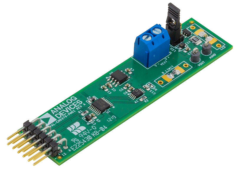
CN0370

16-Bit, Single-Supply LED Current Driver with Less than ±1 LSB Integral and Differential Nonlinearity

CN0370

Circuits from the lab

tooltip Info:Circuits from the lab
16-Bit, Single-Supply LED Current Driver with Less than ±1 LSB Integral and Differential Nonlinearity

Features and Benefits

  • Single-Supply LED Current Driver
  • 16-Bit Resolution
  • ±1LSB Integral and Differential Nonlinearity
  • Low Noise

View Detailed Reference Design external link
Basic Single-Ended, Low Voltage, Low Power, 16-Bit, 100 kSPS ADC Solution

16-Bit, 100 kSPS, Single Supply, Low Power Data Acquisition System

Recently Viewed