MAX20333

RECOMMENDED FOR NEW DESIGNS

Adjustable Current-Limit Switch with Low Power Mode

Extended 0perating Range Up to 22V with Adjustable Current-Limit Modes Provides a Highly Versatile Solution

Viewing:

Overview

  • Flexible Operation
    • Wide Range of Programmable Current Limit (0.2A to 4.75A)
    • Wide Operating Range: 3.5V to 22V (MAX20333/A/ B/C/D/E/F/G/H/I/J/K), 3.3V to 22V (MAX20333L/M/ N)
    • Three Different Current-Limit Modes: NM, HCM, LPM
    • Three Different Current-Limit Behaviors: Autoretry, Latchoff, Continuous
    • Power Good Input
    • Current Monitoring
  • Safe Operation
    • Precision Current Limit
    • Output Short Protection
    • Thermal Protection
    • Flag Output
  • UL 2367 Recognized–File No. E211395
    • MAX20333/A/F/G Only
    • 4.9A/100W Maximum
  • Power Savings
    • Low Power Mode (LPM) with Output Short Protection

The MAX20333/A/B/C/D/E/F/G/H/I/J/K/L/M/N programmable current-limit switches feature internal current limiting to prevent damage to host devices due to faulty load conditions. These current limit switches feature a low 23mΩ (typ) on-resistance and operate from a +3.5V to +22V iinput voltage range (MAX20333/A/B/C/D/E/F/G/H/I/J/K), or +3.3V to +22V input voltage range (MAX20333L/M/N).

The MAX20333 family has three working modes: normal mode (NM), high current mode (HCM), and low power mode (LPM). In NM, the device offers a programmable current-limit protection from 0.2A to 4.75A. The current-limit threshold can be programmed by connecting a suitable resistor to the SETI bump. When the current reaches the programmed threshold, the part prevents the current to further increase. The device can react in three different ways while in current limit: autoretry, latchoff, and continuous. The voltage on the SETI bump is proportional to the current flowing out of the OUT bump at any time and can be read by an ADC.

In high current mode (HCM), the current-limit threshold is multiplied by two, with an internal upper limit set at 5.5A. The voltage on SETI is proportional to the current flowing into IN, but multiplied by a factor 0.5. In low power mode (LPM), the current consumption of the part is dramatically reduced, and the on-resistance is 420mΩ (typ), while still offering an overcurrent protection. The switch is open when the current flowing through the switch exceeds 0.4A (typ).

The devices are available in a 15-bump (2.1mm x 1.52mm) WLP package and operate over the -40°C to +85°C extended temperature range.

Applications

  • Battery Disconnect Switch
  • General Power Supply Switch
  • USB Port Protection Switch

MAX20333
Adjustable Current-Limit Switch with Low Power Mode
MAX20333, MAX20333A: Typical Application Circuit
Add to myAnalog

Add product to the Products section of myAnalog (to receive notifications), to an existing project or to a new project.

Create New Project
Ask a Question

Documentation

Learn More
Add to myAnalog

Add media to the Resources section of myAnalog, to an existing project or to a new project.

Create New Project

Software Resources

Can't find the software or driver you need?

Request a Driver/Software

Tools & Simulations


Evaluation Kits

MAX20333EVKIT

Evaluation Kit for the MAX20333, MAX2033A, MAX20333B, MAX20333C, MAX20333D, MAX20333E, MAX20333F, MAX20333G, MAX20333H, MAX20333I, MAX20333J, MAX20333K, MAX20333L, MAX20333M, MAX20333N

Features and Benefits

  • 3.5V to 22V Operating Voltage Range (3.3V to 22V for MAX20333L/M/N)
  • Output and Flag LED Reading
  • Adjustable Current Limit Setting
  • Adjustable Blanking Time (PBT version)
  • Proven PCB Layout
  • Fully Assembled and Tested

Product Details

The MAX20333 evaluation kit (EV kit) is a fully assembled and tested circuit board that demonstrates the MAX20333 0.2A to 4.75A adjustable current-limit switch device. The EV kit comes with the MAX20333ENL+ installed. The EV kit board can also be used to evaluate MAX20333A/B/C/D/E/F/G/H/I/J/K/L/M/N.

Applications

  • Battery Disconnect Switch
  • General Power Supply Switch
  • USB Port Protection Switch

MAX20333EVKIT
Evaluation Kit for the MAX20333, MAX2033A, MAX20333B, MAX20333C, MAX20333D, MAX20333E, MAX20333F, MAX20333G, MAX20333H, MAX20333I, MAX20333J, MAX20333K, MAX20333L, MAX20333M, MAX20333N

Reference Designs

CN0590 ANGLE evaluation board web
CN0590 Circuits from the lab

Galvanic Isolation of USB High Speed Type-C Connector

Features and Benefits

  • USB 2 High Speed Isolated Retimer
  • Type-C Connectivity
  • Small Form Factor
  • High Efficiency 2.5W Isolated Power
  • Automatic Power Path Selectors with Integrated Protections for Optional External Power
Figure 1. CN0585 Simplified Block Diagram
CN0585 Circuits from the lab

Quad Channel, Low Latency, Data Acquisition and Signal Generation Module

Features and Benefits

  • 4 Analog Input Channels with Configurable Voltage Ranges
  • 4 Analog Output Channels with Configurable Voltage Ranges
  • 200 ns Latency between ADC Measurement and DAC Settling
  • Analog Front End Interface Connector
  • Modeling and Simulation Compatible with MATLAB and Python
  • FMC Connector Interface to FPGA

Part Used


Resources


Design & Integration Tools


Videos

  • lazy blur
    VIDEO · 2023-04-03 03:08
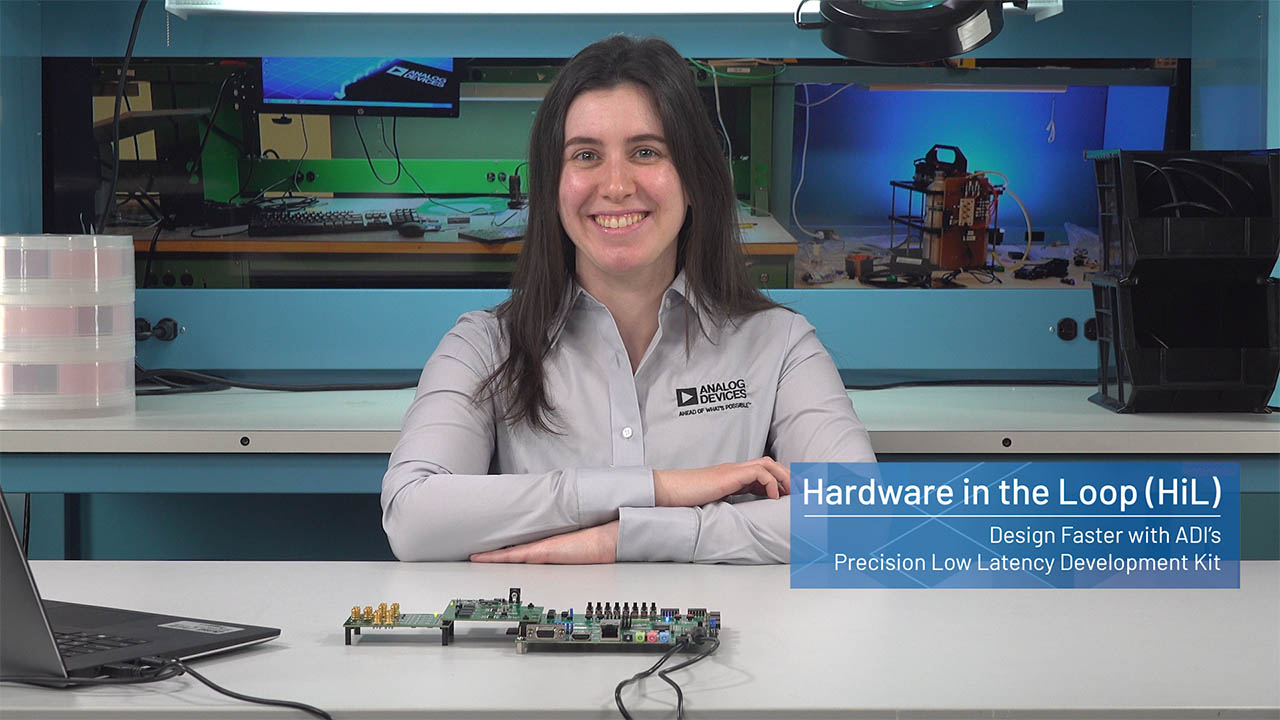
    Personalized Low Latency Hardware in the Loop (HiL) Solution
  • lazy blur
    VIDEO · 2022-10-31 03:03
    Low Latency Test and Measurement Kit – Hardware in the Loop
CN0590
Galvanic Isolation of USB High Speed Type-C Connector
CN0590 ANGLE evaluation board web
CN0590 TOP evaluation board web
CN0590 BOTTOM evaluation board web
Figure 1. CN0590 Simplified Block Diagram
CN0585
Quad Channel, Low Latency, Data Acquisition and Signal Generation Module
Figure 1. CN0585 Simplified Block Diagram
EVAL-CN0585-FMCZ Angle View
EVAL-CN0585-FMCZ Bottom View
EVAL-CN0585-FMCZ Top View

Latest Discussions

Recently Viewed