Overview
Design Resources
Design & Integration File
- Schematic
- Bill of Materials
- Gerber Files
- Layout Files (Allegro)
- Assembly Drawing
Evaluation Hardware
Part Numbers with "Z" indicate RoHS Compliance. Boards checked are needed to evaluate this circuit.
- EVAL-ADICUP360 ($52.97) Arduino Form Factor Development Board
- EVAL-CN0395-ARDZ ($100.05) VOC Gas Detector
Device Drivers
Software such as C code and/or FPGA code, used to communicate with component's digital interface.
Features & Benefits
- Complete Volatile Organic Compound (VOC) Detector
- Constant Voltage, Current, Resistance, Temperature, Heater Control Options
- Wide range sense resistor measurement
- On board temperature and humidity sensor
Product Categories
Markets and Technologies
Parts Used
Documentation & Resources
-
EVAL-CN0395-ARDZ Shield10/16/2018WIKI
Circuit Function & Benefits
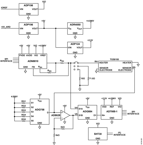
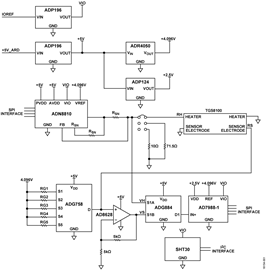
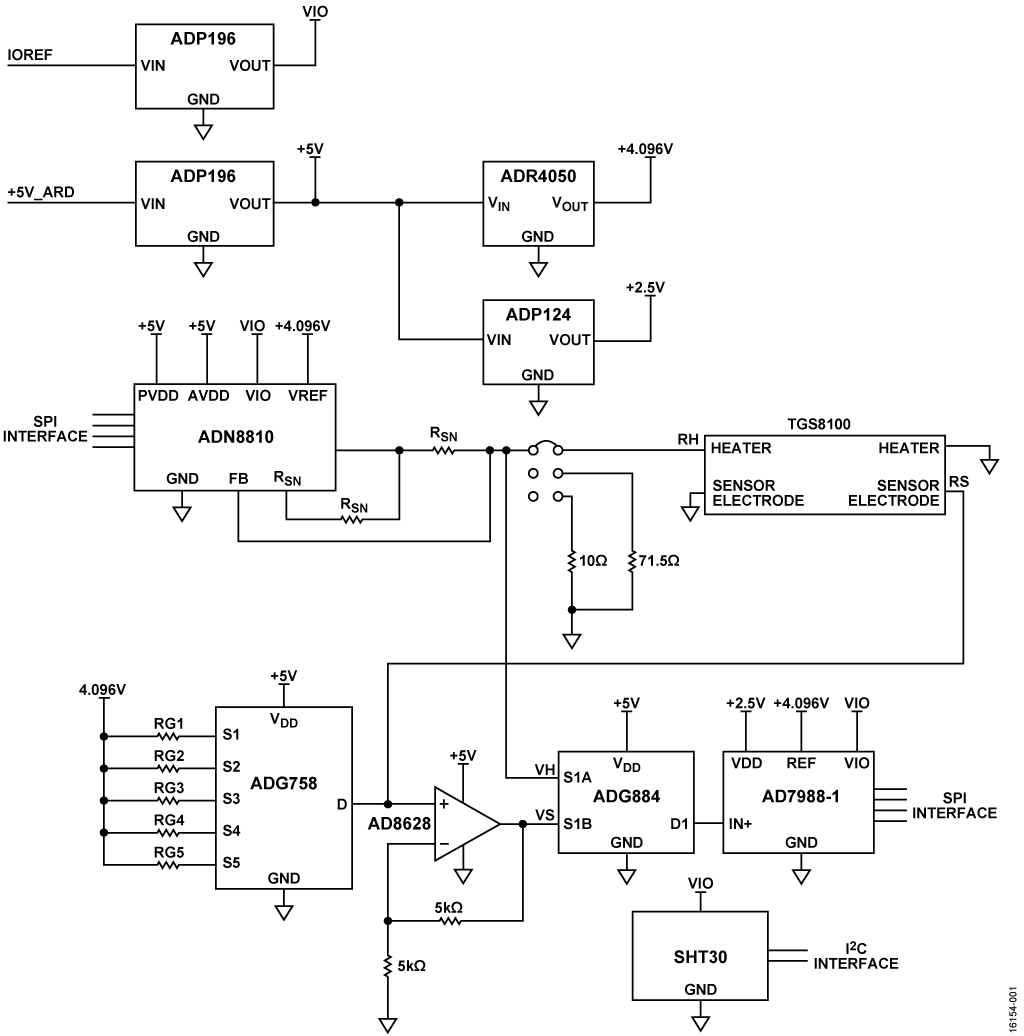
The circuit shown in Figure 1 measures indoor air quality by using a metal-oxide sensor to detect gases composed of volatile organic compounds. The sensor is composed of a heating resistor and a sensing resistor. When the sense resistor is heated, its value changes as a function of the concentrations of different gases.
The circuit uses a 12-bit, current output digital-to-analog converter (DAC) for precision control of the heater current, and the flexible software allows the heater to operate in one of the following four modes: constant current, constant voltage, constant resistance, and constant temperature.
The circuit is able measure a wide range of sense resistance values by using a software-selectable, five range resistor divider. The board also includes a temperature and humidity sensor that is used for compensating the gas concentration value.
Circuit Description
The circuit is optimized for the Figaro TGS8100 sensor, which is comprised of a MOS sensing chip and an integrated heater formed on a silicon substrate using MEMS technology. Other MOS sensors can be used by making appropriate changes in the hardware and software.
Testing was done using carbon monoxide in a gas chamber. The results were correlated to the data sheet specifications of the sensor.
Heater Driver
The ADN8810 is a 12-bit current source with adjustable output current of up to 300 mA. The full-scale current is set with the two output sense resistors. Choosing these resistors and setting the full-scale current is crucial to the design specifications for the sensor installed on the board. The full-scale current must be set not to violate the maximum ratings of the sensor to avoid possible failures.
Using 41.2 Ω sense resistors, the full-scale current of the board is set to approximately 9.94 mA, which is a safe upper limit for the TGS8100 sensor where the recommended operating current is 8 mA. The calculation for the full-scale current as a function of the sense resistor values is given by

where:
VREF is the voltage reference of the circuit (4.096 V).
RSN is the value of the sense resistors.
The full-scale accuracy of the ADN8810 without calibration is 1%. If greater accuracy is required, the full-scale current output can be calibrated using the 71.5 Ω or 10 Ω precision resistors and the P2 jumper.
All operations (constant current, constant voltage, constant resistance, and constant temperature modes) maintain the values of the specified parameter by controlling the amount current passing through the heating element and measuring the heater voltage with the AD7988-1 analog-to-digital converter (ADC).
Relationship Between Heater Resistance and Heater Temperature
The heater resistance, RH_T, is related to the heater temperature, TH, by the following equation:

where:
RH_0 is the heater resistance at ambient temperature, T_0.
TH is the heater temperature.
ALPHA is the sensor dependent constant.
From the TGS8100 data sheet, the following nominal values are obtained: VH = 1.8 V, RH_0 = 110 Ω at T_0 = 20°C. For T_H = 360°C, RH_T = 225 Ω. The constant, ALPHA, is then determined by substitution and solving the previous equation yielding ALPHA = 0.003074.
The equation can be rearranged and solved for TH as a function of RH:

Before setting the mode values, the actual heater resistance, RH_A, at ambient temperature, T_A, is first determined. This value is determined by applying 8 mA to the heater and measuring the heater voltage, VH_A, within 20 μs of the application of the current. At this point the heater is still at ambient temperature. The ambient heater resistance is calculated from RH_A = VH_A/8 mA. The ambient temperature, T_A, and the humidity, HUM, is also recorded.
The previous equations must be modified slightly, because the actual ambient temperature, T_A, can be different from the data sheet value, T_0 = 20°C. With the correction factor added, the two equations become

Heater Modes of Operation
The following sections describe the heater modes of operation in more detail.
Constant Heater Voltage
Constant heater voltage mode is the most common mode of operation. The recommended voltage for the TGS8100 sensor is 1.8 V ± 2%. An iterative program adjusts the heater current, IH, until the measured heater voltage is 1.8 V. The corresponding heater resistance, RH_T, is then calculated from RH_T = VH/IH. The corresponding heater temperature can then be calculated from Equation 5.
Constant Heater Current
The desired heater current, IH, is set in the ADN8810 DAC. The heater voltage, VH, is measured. The heater resistance is calculated from RH_T = VH/IH. The corresponding heater temperature is then calculated from Equation 5.
Constant Heater Temperature
The heater resistance, RH_T corresponding to the desired heater temperature, TH, is calculated using Equation 4. An iterative program adjusts the heater current, IH, and measures the heater voltage, VH, until the desired heater resistance of VH/IH = RH_T is reached.
Constant Heater Resistance
An iterative program adjusts the heater current, IH, and measures the heater voltage, VH, until the desired heater resistance of VH/IH = RH_T is reached. The corresponding heater temperature is then calculated using Equation 5.
Sense Resistor Measurement
The resistance value of the sensing element of the sensor can be determined using the following equation:

where:
RS is the resistance of the sensing element.
VS is the voltage across RS with respect to ground.
RG is the range setting resistor used in the voltage divider.
VREF is the value of the reference voltage (4.096 V).
To cover RS ranges from 30 Ω to 30 MΩ, one of five RG resistors are selected using the ADG758 low voltage, CMOS, analog multiplexer. The circuit uses the S1 to S5 channels with corresponding RG resistor values of 8.87 kΩ, 39.2 kΩ, 110 kΩ, 2.74 MΩ, and 33 MΩ, respectively.
Using the RG resistors in a voltage divider with RS and VREF, the value of the RS sense resistor can now be determined using Equation 6.
The output voltage from the voltage divider of the sense resistor is amplified by a factor of 2 to match the input range of the AD7988-1 ADC using the AD8628, an ultralow offset, drift and bias current op amp.
The AD7988-1 is a low power, 100 kSPS 16-bit, successive approximation ADC used to convert the voltage readings from the heating and sensing element of the sensor.
The ADG884 is a software selectable low voltage CMOS dual single pole, double throw switch used to switch between voltage readings from the heating and sensing element of the sensor.
The ADR4540 is an ultralow noise, low power voltage reference. It produces a high accuracy 4.096 V reference voltage to the ADN8810, AD7988-1, and the RG divider network with excellent temperature stability and low output noise, consuming only a maximum of 950 μA.
The ADP196 is a logic-controlled high side power switch that is used to fully shut down the whole circuit using the digital input/output pins from the ADICUP360, dropping the consumption of the circuit to 400 µW. This feature allows a power down function for the board by using a digital input/output pins, making it an excellent candidate for a low power solutions.
The ADP124 is a low quiescent current, low dropout linear regulator that is used as the 2.5 V supply voltage for the AD7798-1.
The circuit also has an on-board temperature and humidity sensor, SHT30, from Sensirion, which is used for compensation in making the calculations for the concentration of gasses.
The combinations of these ICs create a low power solution for measurement of volatile organic compounds in indoor applications.
Conversion of Sensor Resistance to Gas Concentration
The TGS8100 sensor data sheet shows typical concentration curves as a function of RS/R0, where R0 is the sense resistance value with no gas present. The curve for carbon monoxide (CO) gas can be approximated by two equations depending on the RS/R0 ratio. The equations apply with CO concentration levels from 1 ppm to 100 ppm.
For RS/R0 between 0.05 and 0.6,

For RS/R0 between 0.6 and 0.95,

Heater Control Software
The demo software for the CN-0395 displays the modes of heater operation, the resistance of sense resistance readings at T_0 or clean air, current sense resistance reading for calculations, and calculated gas concentrations.
There are four different heater modes of operation: constant voltage, constant current, constant resistance, and constant temperature.
In constant voltage mode, it is assumed that the initial heater resistance is at 225 Ω, and the desired heater voltage is maintained to a 0.5% accuracy by calculating the error voltage and adjusting the output current accordingly

where:
VH is the user input of the voltage to be maintained.
IH1 is the initial current that is set of the ADN8810.
VH1 is read across the heating resistor, and the error calculation is as follows:

where:
VH is the desired heater voltage.
VH1 is the voltage read across the heating resistor.
If the error does not fall within the specified tolerance, a new heater current is set to the ADN8810. The new heater current is calculated using the following equation:

where:
IH2 is the heater current for the second iteration.
IH1 is the heater current for the first iteration.
E1 is the voltage error from the first iteration.
Multiple iterations may be needed to fall within the range of desired voltage; however, if the error falls within 0.5%, the iterations stop.
Sensor Resistance Measurement Software
The software measures the sensor resistance, RS, using Equation 6. The algorithm steps through the gain resistor ranges, starting with the highest range (RG1 = 33 MΩ), until the correct range is reached. After RS is determined, it is converted into gas concentration using the equation described in the following section.
Test Results
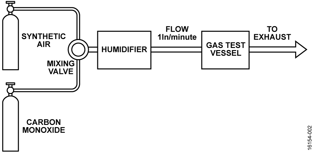
The circuit was tested in a gas test vessel, being exposed to various concentrations of CO gas. To achieve various concentrations, carbon monoxide is mixed with synthetic air at a specified ratio. The gas mixture is passed through a humidifier and is purged to the gas test vessel at a constant rate of 1 ln/min, as shown in Figure 2.
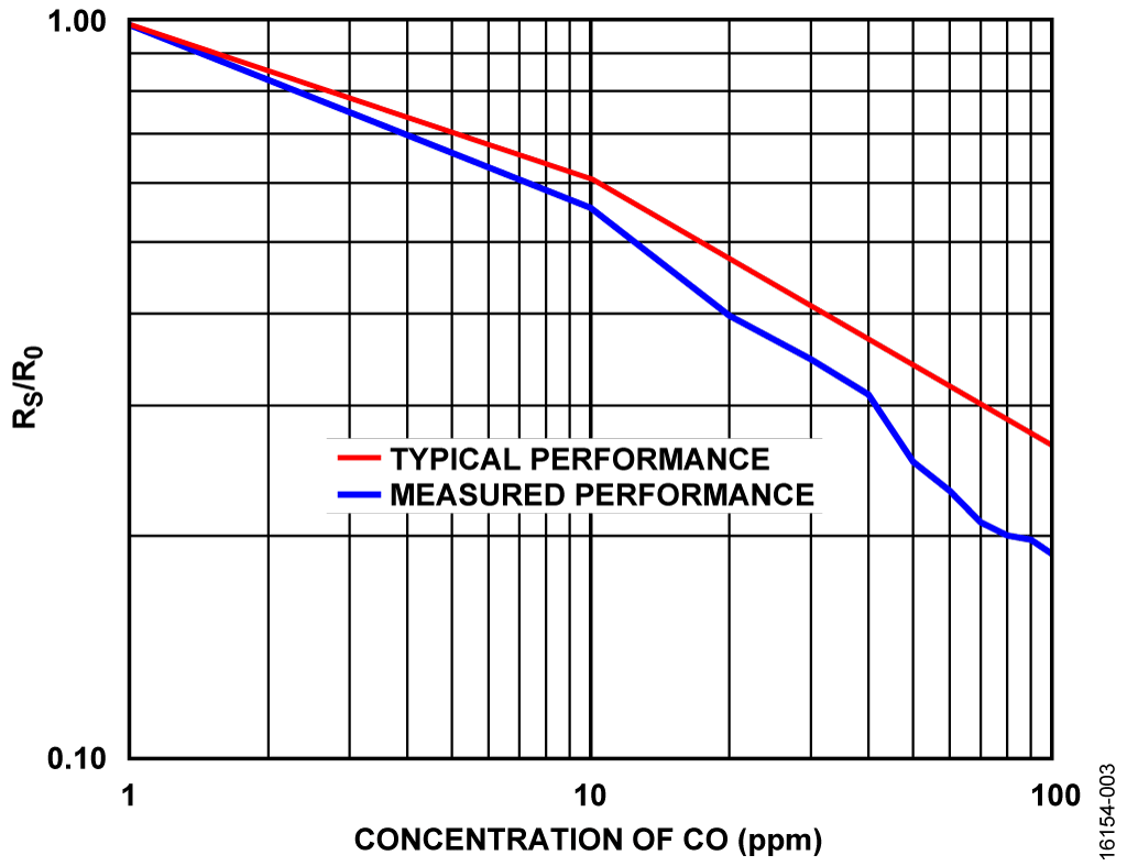
The RS/R0 vs. gas concentration results for the test using the setup are shown in Figure 3 in blue. The red trace shows the typical concentration values predicted by the approximations using Equation 7 and Equation 8. The difference in RS/R0 at 100 ppm is approximately 25%.
To achieve more accurate concentration results, calibrate the system in a chamber using known concentrations of the target gas. Variations between sensors, sensor contamination due to exposure to impurities, aging effects, temperature, relative humidity, stabilization time, and purity of the synthetic mixing air all affect the final results.
An important factor in obtaining consistent results is to let the sensor stabilize in ambient air for at least 30 minutes with power applied to the heater before taking the R0 measurement. Sufficient stabilization time must also be allowed at each concentration level. For the results shown in Figure 3, the R0 stabilization time was 1 hour, and the stabilization time at each concentration level was 10 minutes. Additional stabilization time may improve accuracy.
Board Layout Considerations
It is important to carefully consider the power supply and ground return layout on the board. Design the printed circuit to have separate analog and digital sections. If the circuit is used in a system where multiple devices require an analog ground to digital ground connection, make the connection at only one point. Bypass the power supplies to all components with at least 0.1 μF capacitors. These bypass capacitors must be as physically close as possible to the device, with the capacitor ideally right up against the device. Choose the 0.1 μF capacitor to have low effective series resistance (ESR) and low effective series inductance (ESL), such as ceramic capacitors. This 0.1 μF capacitor provides a low impedance path to ground for transient currents. The power supply line must also have as large a trace as possible to provide a low impedance supply path. Use proper layout, grounding, and decoupling techniques to achieve optimum performance (see the MT-031 Tutorial, Grounding Data Converters and Solving the Mystery of AGND and DGND, and the MT-101 Tutorial, Decoupling Techniques).
A complete set of documentation for the EVAL-CN0395-ARDZ including schematics, layouts, and bill of materials can be found at www.analog.com/CN0395-DesignSupport.
Common Variations
With the trade-off of complexity and cost, the ADN8810 can be replaced with a current source controlled by a DAC.
For a higher resolution ADC, use the AD7989-1. For a higher sampling rate ADC, use the AD7988-5 or AD7989-5.
Another good candidate for an 8:1 multiplexer is the ADG5208F, which has added features of latch-up immunity and overvoltage detection and protection.
For a lower offset voltage with the tradeoff of power, use the ADA4528-1.
For a faster enable time, use the ADP195 instead of the ADP196.
For a higher accuracy 2.5 V supply, use the ADP7156 or ADP7158.
For a lower power consumption 4.096 V reference voltage with lower initial accuracy, use the ADR4530.
Circuit Evaluation & Test
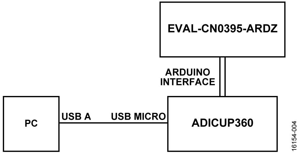
This circuit uses the EVAL-CN0395-ARDZ circuit board and the EVAL-ADICUP360. The EVAL-CN0395-ARDZ is stacked on top of the EVAL-ADICUP360 board using the Arduino-compatible pins.
Equipment Needed
The following equipment is needed:
- PC with a USB port and Windows® 7 (64-bit), Windows 8 (64-bit), or Windows 10 (64-bit)
- EVAL-CN0395-ARDZ circuit evaluation board
- EVAL-ADICUP360 evaluation board or equivalent Arduino interface
- USB A to USB micro cable
- EVAL-ADICUP360 software (IDE)
- EVAL-CN0395-ARDZ sample code
Getting Started
Load the sample code onto the EVAL-ADICUP360 IDE by following the EVAL-ADICUP360 Tool Chain Setup User Guide.
Functional Block Diagram
Figure 4 shows the functional block diagram of the test setup.
Setup
Connect the EVAL-CN0395-ARDZ by mounting it on top of the EVAL-ADICUP360 board using the Arduino-compatible headers with their corresponding headers. Then connect the USB cable from the debug port of the EVAL-ADICUP360 to the USB port of the PC.
Test
With the sample code built and loaded onto the EVALADICUP360 and the EVAL-CN0395-ARDZ mounted on top, the device communicates with the PC and displays the reading from each of the channels. The circuit can be tested by exposing the board in clean air for the initial reading and then exposing it to different concentrations of volatile organic compound gasses.
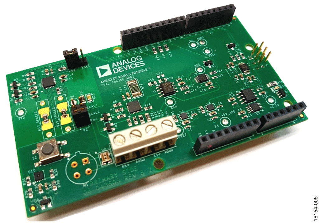
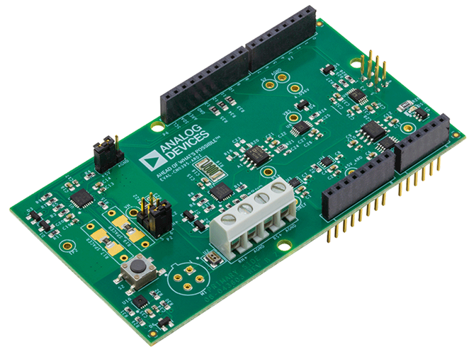
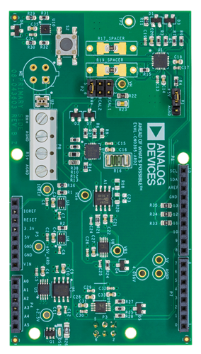
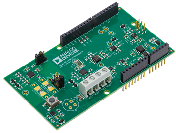
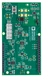
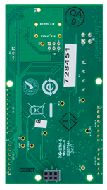
Figure 5 shows a photo of the EVAL-CN0395-ARDZ circuit evaluation board.
Information and details regarding test setup and how to use the EVAL-ADICUP360 and the sample code for data capture can be found in the CN0395 User Guide.
Information regarding the EVAL-ADICUP360 board can be found in the EVAL-ADICUP360 Tool Chain Setup User Guide.
