MAX32690
新規設計に推奨産業およびウェアラブル機器向け、FPU搭載Arm Cortex-M4マイクロコントローラおよびBluetooth LE 5
- 製品モデル
- 12
- 1Ku当たりの価格
- 最低価格:$19.49
製品情報
- バッテリ駆動アプリケーション用の超高効率マイクロコントローラ
- FPU内蔵120MHz Arm Cortex-M4プロセッサ
- データ処理のオフロードが可能な超低電力32ビットRISC-V(RV32)コプロセッサ
- 複数の内蔵低電力発振器
- 32.768kHz RTCクロック(外部水晶発振子が必要)
- 3.25MBの内部フラッシュメモリ、1MBの内部SRAM
- アクティブモード:85μW/MHz(1.1V時)
- レベル変換器を必要としない1.8Vおよび3.3V I/O
- 外部フラッシュおよびSRAM拡張インターフェース
- Bluetooth 5.2 LE無線
- 完全オープン・ソースのBluetooth 5.2 スタックが利用可能
- 高スループット(2Mbps)モード
- ロングレンジ(125kbpsおよび500kbps)モード
- 受信感度:-97dBm、送信出力:+4.5dBm
- シングル・エンド・アンテナ接続(50Ω)
- 32MHz外部水晶発振子が必要
- 最適なペリフェラル・ミックスによってプラットフォームの拡張性を提供
- 16チャンネルDMA
- 最大5つのQuad-SPIコントローラ/ターゲット
- 最大4つのフロー制御機能付きUART
- 最大3つのI2Cインターフェース
- I2Sインターフェース
- 温度センサー・チャンネルを備えた、最大8つの外部チャンネルの12ビット1Msps SAR ADC
- USB 2.0ハイスピード・デバイス
- 最大16個のパルス・トレイン・エンジン
- 8mAドライブを備えた最大4つの32ビット/デュアル16ビット・タイマー
- 最大2つの32ビット/デュアル16ビット低電力タイマー
- 2つのCAN 2.0Bコントローラ
- 最大4つのマイクロパワー・コンパレータ
- 1-Wireコントローラ
- IP/データ・セキュリティ用暗号ツールボックス(CTB)
- AES-128/192/256、SHA-2エンジン、MAA、TRNG
- 充実したセキュリティ機能
- Armメモリ保護ユニット(MPU)
- 外部SPIメモリ用メモリ復号完全性ユニット(MDIU)
- 物理的複製防止機能(PUF)
- 128ビット固有シリアル・ナンバー(USN)
- オプションのセキュア通信プロトコル・ブートローダ (SCPBL)
MAX32690マイクロコントローラ(MCU)は、Arm® Cortex®-M4F CPU、大容量のフラッシュおよびSRAMメモリ、Bluetooth® 5.2 Low Energy(LE)無線機能を備えた先進的なシステム・オン・チップ(SoC)です。このデバイスは、IoTアプリケーションに必要な処理能力とコネクティビティを兼ね備えています。
MAX32690は、-40℃~+105℃の温度範囲での動作が保証されており、産業環境に最適です。このデバイスは、68ピンTQFN-EP(0.40mmピッチ)、140バンプWLP(0.35mmピッチ)、および144ピンCTBGA(0.8mmピッチ)のパッケージで提供されています。
内蔵のBluetooth 5.2 Low Energy(LE)無線は、ロングレンジ(符号化)モードおよび高スループット・モードに対応しています。RISC-Vコアは、オプションでタイミングが重要なコントローラ・タスクを処理するため、プログラマはBluetooth LEの割込みレイテンシに注意する必要がなくなります。
内部コードおよびSRAM領域は、2つのクワッドSPI execute-in-place(SPIXFおよびSPIXR)インターフェースを介して、それぞれ最大512MBまでオフチップで拡張可能です。
暗号ツールボックス(CTB)は、モジュロ演算アクセラレータ(MAA)、高度暗号化規格(AES)エンジン、TRNG、およびSHA-2エンジンを提供します。また、このデバイスには、128ビットの固有シリアル・ナンバー(USN)、物理的複製防止機能(PUF)、セキュアな不揮発性キー・ストレージ、SPIXFおよびSPIXR向けのメモリ復号完全性ユニット(MDIU)、ならびにArmメモリ保護ユニット(MPU)など、幅広いセキュリティ機能が搭載されています。オプションのセキュア通信プロトコル・ブートローダ(SCPBL)は、改ざん不能な信頼の基点、ECDSAを用いたフラッシュ整合性検証によるセキュア・ブート、およびセキュアなファームウェア更新機能を提供します。
このデバイスでは、複数のQSPI、UART、CAN 2.0B、I2Cシリアル・インターフェースをはじめ、オーディオ・コーデックに接続するための1つのI2Sポートなど、多くの高速インターフェースがサポートされています。ほとんどのインターフェースは、メモリ(フラッシュまたはSRAM)と周辺機器間のDMA駆動による転送をサポートしています。12入力(外部8入力)の12ビットSAR ADCは、最大1Mspsでアナログ・データをサンプリングします。
アプリケーション
- フィットネス/ヘルスケア関連のウェアラブル・デバイス
- ポータブルおよびウェアラブルのワイヤレス医療機器
- 資産トラッキング
- 工業用センサーおよびネットワーク
ドキュメント
データシート 2
ユーザ・ガイド 2
アプリケーション・ノート 1
デバイス・ドライバ 1
アナログ・ダイアログ 3
ウェブキャスト 1
| 製品モデル | ピン/パッケージ図 | 資料 | CADシンボル、フットプリント、および3Dモデル |
|---|---|---|---|
| MAX32690EXE+ | Chip Array Thin Core Ball Grid Array | ||
| MAX32690EXE+T | Chip Array Thin Core Ball Grid Array | ||
| MAX32690EXEBL+ | Chip Array Thin Core Ball Grid Array | ||
| MAX32690EXEBL+T | Chip Array Thin Core Ball Grid Array | ||
| MAX32690GTK+ | LFCSP | ||
| MAX32690GTK+T | LFCSP | ||
| MAX32690GTKBL+ | LFCSP | ||
| MAX32690GTKBL+T | LFCSP | ||
| MAX32690GWE+ | WLCSP | ||
| MAX32690GWE+T | WLCSP | ||
| MAX32690GWEBL+ | WLCSP | ||
| MAX32690GWEBL+T | WLCSP |
これは最新改訂バージョンのデータシートです。
ソフトウェア・リソース
デバイス・ドライバ 1
EdgeBench 新規
EdgeBench is a secure, cloud‑based platform for remotely benchmarking and evaluating AI/ML models on Analog Devices’ edge hardware.
詳細を表示CodeFusion Studio™
各種の賞を獲得したCodeFusion Studio(CFS)は、AI対応組込みシステムの開発を加速する組込みソフトウェア開発プラットフォームです。
詳細を表示評価用ソフトウェア 1
MAX32xxx-MAX78xxx MSDK Software
必要なソフトウェア/ドライバが見つかりませんか?
ツールおよびシミュレーション
評価用キット


MAX32690評価用キット
資料
ソフトウェア


Scalable BMS Kit for Cell and Pack Monitoring
資料
ソフトウェア


ADIN6310 Field Switch Reference Design User Guide
資料


Arduino Form-factor Development Platform Based on MAX32690 ARM Cortex-M4 Microcontroller
資料
ソフトウェア


Complete Ethernet-APL Field Device Platform
資料
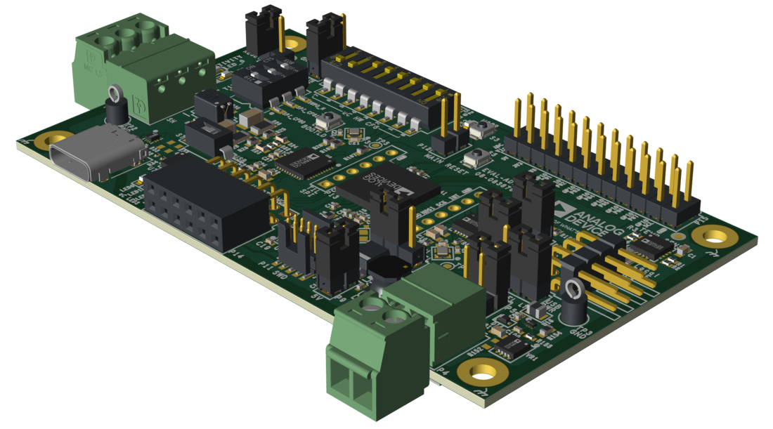
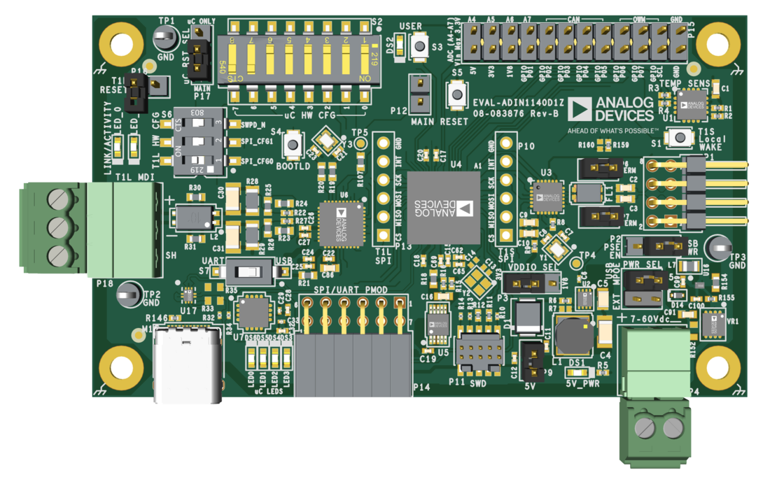
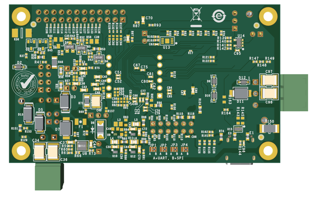
Evaluating the ADIN1140 10BASE-T1S Industrial Multidrop Evaluation Platform Board