
AN-2637: Basic Functional Testing for ADIN3310/ADIN6310 Switches
Background
This application note describes guidance for verifying basic Ethernet connectivity in systems that use Analog Devices, Inc., Ethernet switches (ADIN3310/ADIN6310) together with external physical layer (PHY) devices (ADIN1100/ADIN1200/ADIN1300).
In these systems, the Ethernet switch manages traffic forwarding, while the PHY provides the physical interface between the switch media access control (MAC) and the network media. The procedures described in this document are intended for early hardware bring-up and manufacturing validation, where the primary goal is to confirm that the Ethernet transmit (Tx) and receive (Rx) data paths are operating correctly.
Successful transmission and reception of Ethernet frames on ports connected to a PHY is a key indicator of correct basic operation. This confirms that the switch MAC, the PHY, and their interfaces are functioning as expected at a fundamental level.
These tests are designed to quickly identify common board-level issues, such as incorrect routing, soldering defects, or configuration errors, that can prevent link establishment or proper frame transmission. By following the methods outlined here, users can rapidly establish Ethernet connectivity, verify traffic routing, and confirm PHY configuration before moving on to more advanced diagnostics, protocol validation, or time-sensitive networking (TSN) verification.
Although this document focuses on systems that use external PHY devices, the same basic validation approach can also be applied to MAC-to-MAC connections, where applicable.
Device Overview
The ADIN3310 and ADIN6310 are managed Ethernet switches designed for industrial networking applications. They support flexible Ethernet connectivity across multiple physical media, including gigabit Ethernet and single pair Ethernet (SPE).
Each switch integrates multiple ports and supports advanced networking features such as TSN, redundancy mechanisms, and configurable traffic forwarding. Per-port Ethernet statistics counters are provided to monitor traffic flow by tracking transmitted and received frames.
In addition to standard switching functionality, the ADIN3310 and ADIN6310 support the generation and forwarding of custom Layer 2 Ethernet frames. This capability is particularly useful during system bring-up and connectivity testing, where controlled traffic generation simplifies functional verification.
The switch also provide access to PHY configuration through an integrated MDIO interface. This allows a host processor to read and write PHY register values for connected devices. Using available driver APIs, the host can verify key operating parameters such as link speed, duplex mode, and autonegotiation status.
The MDIO-based access supports both Analog Devices PHYs, including the ADIN1300 (gigabit Ethernet), ADIN1200 (fast Ethernet), and ADIN1100 (10BASE-T1L), and non-ADI PHY devices, providing flexibility for systems that use mixed PHY configurations.
Test Setup Requirements
This application note uses the EVAL-ADIN6310T1LEBZ evaluation board as a reference platform to demonstrate basic Ethernet functional testing. While the examples are specific to this board, the same test approach can be applied to other hardware platforms by adapting the software and port configuration as required.
Two test configurations are described as follows:
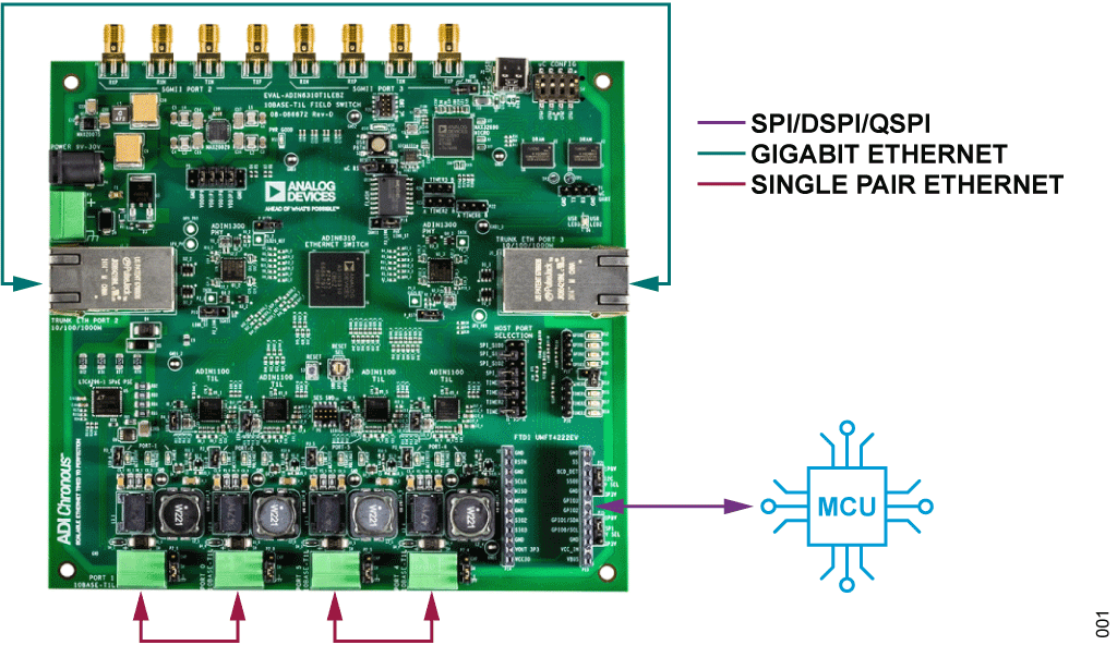
- Single-board (Figure 1)
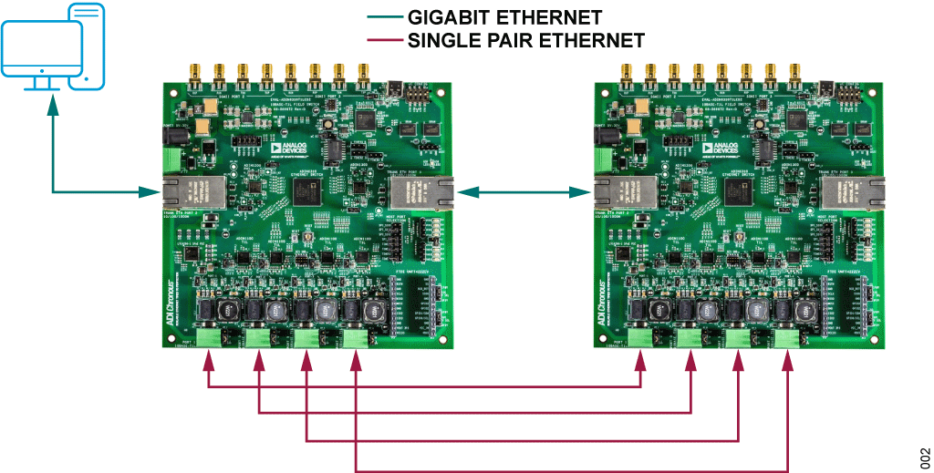
- Multiboard (Figure 2)
Both configurations require a host processor to configure and manage the ADIN6310 Ethernet switch through one of its supported interfaces, including serial peripheral interface (SPI), dual SPI, quad SPI, or an Ethernet interfaces.
Single-Board Configuration
In Figure 1, one EVAL-ADIN6310T1LEBZ board is used. This board has six Ethernet ports, two gigabit Ethernet ports implemented with ADIN1300 PHYs and four 10BASE-T1L ports implemented with ADIN1100 PHYs. The gigabit Ethernet ports are connected to each other, and the SPE ports are paired.
The on-board MAX32690 microcontroller configures the ADIN6310 via the SPI interface. Because several ports are internally connected, this configuration introduces multiple network loops. Without proper configuration, these loops can result in a traffic storm and prevent normal operation.
To avoid this condition, loop protection must be configured on the switch during initialization.
Note: at power-up, only the host interface (SPI or MAC) is enabled. The switch then waits for the host to configure the remaining ports as part of the initialization routine. Loop protection must be applied before the PHYs establish a link.
Multiboard Configuration
In Figure 2, multiple EVAL-ADIN6310T1LEBZ boards are connected to create a more complex network topology. A host is connected to the first board, and a second board is daisy-chained to the first, forming a linear topology.
As with the single-board configuration, this setup also introduces network loops. Loop protection is therefore required to prevent traffic from flooding indefinitely and overwhelming the system.
Note: this configuration may impose limitations on functional testing, as an odd number of ports may be available depending on how the boards are interconnected.
PHY Diagnostic
The ADIN3310/ADIN6310 switches provide direct access to PHY registers through the management data input/output (MDIO) bus. This access is available using the following APIs:
- SES_MX_ReadPhyReg: reads PHY register values
- SES_MX_WritePhyReg: writes to PHY registers
Direct MDIO access enables low-level verification and debugging of PHY configurations beyond what is exposed through higher-level switch APIs. This capability allows users to confirm register settings, diagnose link issues, and validate PHY behavior during early bring-up.
The same mechanism can be used for both Analog Devices PHYs and third-party PHY devices, providing flexibility for systems that include non-ADI components.
Network Loop Protection
Network loop protection prevents traffic from continuously circulating through the network and disrupting normal operation.
Note: loop protection must be configured immediately after initializing the ports of ADIN3310/ADIN6310 and before the PHYs establish a link.
Loop protection is implemented using the SES_ApplyForwardMask or SES_MX_ApplyForwardMask application programing interface (API). These APIs define a forwarding mask on a per-port basis, specifying which egress ports are allowed to receive frames arriving on a given ingress port.
The forwarding mask can also be configured to block forwarding entirely, ensuring that traffic received on a port is not forwarded to any other ports.
Note: APIs with the SES_MX_ prefix are used in multiple switch configurations and allow the host to specify which switch device is being configured.
In the example code, for the multiboard configuration, forwarding is disabled for Port 0, Port 1, Port 4, and Port 5 by setting their port maps to 0x00. Traffic received on these ports is not forwarded further. Port 2 (0x08) and Port 3 (0x04) are configured to forward traffic to each other, enabling controlled communication for boards in the daisy chain.
The forwarding mask is expressed as a bitmask, where each bit position corresponds to a port number (Bit 0 corresponds to Port 0, Bit 1 to Port 1, Bit 2 to Port 2, Bit 3 to Port 3, Bit 4 to Port 4, and Bit 5 to Port 5). By setting or clearing specific bits in the mask, users control how traffic is forwarded between ports.
/* Apply forward mask to prevent traffic loop */
rv = SES_MX_ApplyForwardMask(0, SES_macPort0, 0x00);
rv = SES_MX_ApplyForwardMask(0, SES_macPort1, 0x00);

/* Forward to second device (Port 3) */
rv = SES_MX_ApplyForwardMask(0, SES_macPort2, 0x08);

/* Forward to host device (Port 2) */
rv = SES_MX_ApplyForwardMask(0, SES_macPort3, 0x04);

rv = SES_MX_ApplyForwardMask(0, SES_macPort4, 0x00);
rv = SES_MX_ApplyForwardMask(0, SES_macPort5, 0x00);
Users are expected to configure forwarding masks according to their own board topology and port connections. For example, ports that are paired in a design are typically configured to forward traffic only to each other, while preventing forwarding to unrelated ports. Similarly, ports that must not participate in traffic forwarding can be configured with a forwarding mask that blocks all egress ports.
In systems that include multiple switches connected in a daisy-chain topology (Figure 2), forwarding masks must be configured such that the traffic from the host can reach downstream switches while preventing unnecessary forwarding to unrelated ports. This ensures controlled traffic flow through the network while avoiding unintended loops.
Frame Generation
The ADIN3310/ADIN6310 switches support transmission of custom Ethernet frames using the SES_XmitFrame or SES_MX_XmitFrame API. These APIs allow users to construct test frames and specify the port on which the frame is transmitted.
In the example provided, the custom frame consists of the following:
- Destination MAC address (first 6 bytes)
- Source MAC address (next 6 bytes)
- EtherType field (last 2 bytes)
The API automatically pads the frame to meet the minimum Ethernet frame size requirement of 64 bytes.
The egress port is defined using the egressPortMap parameter. In the example, this is set to 0x02 corresponding to Port 1.
Using Figure 2 as a reference, the frame is transmitted from Port 1 of Switch (0) and received on Port 1 of Switch (1). The receiving port must be configured to verify frame reception, as described in the Frame Checker section.
// Configure Frame for Transmitter on SES 0
uint8_t packet[] = {
    0x00, 0x0A, 0xCD, 0x11, 0x11, 0x11,
    0x00, 0x0A, 0xCD, 0x22, 0x22, 0x22,
    0x12, 0x34
};

SES_transmitFrameData_t txData0 = {
    .frameType = SES_standardFrame,
    .data_p = &packet,
    .byteCount = sizeof(packet),
    .cb_p = 0,
    .cbParam_p = 0,
    .ses = {
        .generateFcs = 1,
        .xmitPriority = 0,
        .egressPortMap = 0x02,
        .transformId = SES_NO_TRANSFORM,
        .attributeRequest = 0
    }
};

// Transmit Frames on SES 0 - Port 1
rv = SES_MX_XmitFrame(0, &txData0);
rv = SES_MX_XmitFrame(0, &txData0);
rv = SES_MX_XmitFrame(0, &txData0);
rv = SES_MX_XmitFrame(0, &txData0);
rv = SES_MX_XmitFrame(0, &txData0);
Sleep(1000);
Frame Checker
Two methods are available to verify whether a frame has been received on a specific port.
Using Statistics APIs
The first method uses the SES_GetStatistics or SES_MX_GetStatistics API on the receiving device. These APIs provide counters for received bytes, unicast packets, broadcast packets, multicast packets, and other traffic metrics.
These counters can also be used to verify transmitted traffic.
Note: unicast frames transmitted using the frame generation API cannot be distinguished from unicast frames originating from other sources. Both increment the same unicast receive counter.
Using Receive Frames By Mac APIs
The second method uses the SES_RxSesFramesByMac or SES_MX_RxSesFramesByMac API. These APIs register a callback function that is triggered when a frame with a specified destination MAC address is received.
To enable this mechanism, frames must be forwarded to the packet assist engine (PAE). This requires the following steps:
- Adding a static table entry for the target destination MAC address
- Enabling forwarding to the PAE for that entry
In the example, Switch (1) is configured as the receiver.
/* Configure SES 1 as Receiver */
uint8_t macAddr1[6] = {
    0x00, 0x0A, 0xCD, 0x11, 0x11, 0x11
};
uint8_t macMask1[6] = {
    0xFF, 0xFF, 0xFF, 0xFF, 0xFF, 0xFF
};

/* Static Entry Assist Engine Set to 1 */
uint8_t sendToAE = 1;
int32_t index;

rv = SES_MX_AddStaticTableEntryEx(
    1, 0, macAddr1, macMask1,
    0xFFF, 0xFFF, 0, 0,
    0, 0, SES_dynamicTblLookupBasic, 0,
    sendToAE, 0, 0, 0,
    0, dynamicTblNoSequenceOp, 0, SES_IGNORE_FIELD, SES_IGNORE_FIELD, &index
);

if (rv != SES_PORT_OK)
    printf("SES_MX_AddStaticTableEntryEx :: %d\n", rv);

/* Enable Rx Frames by MAC on SES 1 */
/* Receive Frame on SES 1 */
rv = SES_MX_RxSesFramesByMac(
    1, macAddr1,
    SES_REQUEST_PORT_ATTRIBUTE, SES_rxCallback
back
);
if (rv != SES_PORT_OK)
    printf("Receive Frames - FAIL :: %d\n",
rv);
When a matching frame is received, the callback function identifies the port on which the frame arrived and allows the application to track reception events or increment per-port counters.
void SES_rxCallback(int32_t frameLength, uint8_t* frame_p, SES_frameAttributes_t* frameAttributes_p) {
    uint32_t port = frameAttributes_p->port;

    if (port == 0)
        count_port0++;
    else if (port == 1)
        count_port1++;
    else if (port == 2)
        printf("Port 2\n");
    else if (port == 3)
        printf("Port 3\n");
    else if (port == 4)
        count_port4++;
    else if (port == 5)
        count_port5++;
    else
        printf("Error \n");

    printf("Received Packet :: \n");
    for (int i = 0; i < 12; i++) {
        printf("%02X ", frame_p[i]); // Print each element in hexadecimal format
    }
    printf("\n");
    printf("Port :: %d\n", port);
}
After completing a test scenario, the callback can be disabled by removing the static table entry (SES_MX_RmStaticTableEntryByIndex) or updating it to disable forwarding to the PAE. This ensures that only relevant traffic is monitored during each test cycle and avoids unintended callbacks during subsequent tests.
/* Static Entry Assist Engine Set to 0 */
uint8_t sendToAE = 0;

rv = SES_MX_AddStaticTableEntryEx(
    1, 0, macAddr1, macMask1,
    0xFFF, 0xFFF, 0, 0,
    0, 0, SES_dynamicTblLookupBasic, 0,
    sendToAE, 0, 0, 0,
    0, dynamicTblNoSequenceOp, 0, SES_IGNORE_FIELD, SES_IGNORE_FIELD, &index
);

if (rv != SES_PORT_OK)
    printf("SES_MX_AddStaticTableEntryEx :: %d\n", rv);