

ADL8130
推荐用于新设计GaAs, pHEMT, MMIC, 0.01GHz to 8GHz, Low Noise Amplifier
- 产品模型
- 2
概述
- High gain: 25.5dB typical from 0.01GHz to 2GHz
- Low noise figure: <0.6dB typical from 0.5GHz to 2GHz
- Power-down voltage pin (VPD) for enabling and disabling the amplifier
- Single-supply bias
- Extended operating temperature range: −55°C to +125°C
- RoHS-compliant, 2mm × 2mm, 8-lead LFCSP
The ADL8130 is a gallium arsenide (GaAs), pseudomorphic high electron mobility transistor (pHEMT), monolithic microwave integrated circuit (MMIC), wideband low noise amplifier (LNA) that operates from 0.01GHz to 8GHz. The ADL8130 provides a typical gain of 25.5dB from 0.01GHz to 2GHz, a 0.6dB typical noise figure from 0.5GHz to 2GHz, and a typical output third-order intercept (OIP3) of 37dBm from 0.01GHz to 2GHz, requiring only a 90mA supply current (IDQ) from a 5V supply voltage (VDD). Power dissipation can be lowered at the expense of the OIP3 and output power (POUT). The internally matched, DC-coupled RF input (RFIN) and output (RFOUT) pins require external AC coupling capacitors along with a bias inductor on RFOUT. In addition, the RF input is biased through an external inductor connected between the VBIAS pin and RFIN pin.
The ADL8130 is housed in a RoHS-compliant, 2mm × 2mm, 8-lead LFCSP.
参考资料
数据手册 1
用户手册 1
ADI 始终高度重视提供符合最高质量和可靠性水平的产品。我们通过将质量和可靠性检查纳入产品和工艺设计的各个范围以及制造过程来实现这一目标。出货产品的“零缺陷”始终是我们的目标。查看我们的质量和可靠性计划和认证以了解更多信息。
| 产品型号 | 引脚/封装图-中文版 | 文档 | CAD 符号,脚注和 3D模型 |
|---|---|---|---|
| ADL8130ACPZN | 8-lead LFCSP 2 mm × 2 mm × 0.85 | ||
| ADL8130ACPZN-R7 | 8-lead LFCSP 2 mm × 2 mm × 0.85 |
这是最新版本的数据手册
软件资源
找不到您所需的软件或驱动?
申请驱动/软件工具及仿真模型
S-参数 1
评估套件
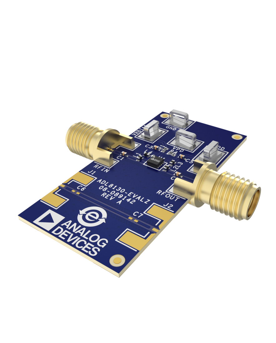
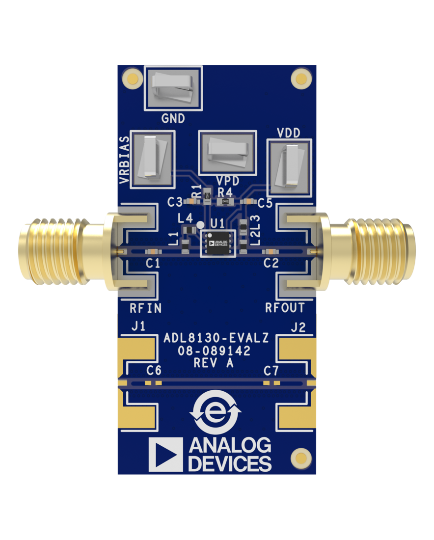

Evaluating the ADL8130 GaAs, pHEMT, MMIC, 0.01GHz to 8GHz, Low Noise Amplifier
资料
最新评论
需要发起讨论吗? 没有关于 ADL8130的相关讨论?是否需要发起讨论?
在EngineerZone®上发起讨论