ADL7075

推荐用于新设计

100MHz to 31GHz, High Survivability, Low Noise Amplifier

Viewing:
产品技术资料帮助

ADI公司所提供的资料均视为准确、可靠。但本公司不为用户在应用过程中侵犯任何专利权或第三方权利承担任何责任。技术指标的修改不再另行通知。本公司既没有含蓄的允许,也不允许借用ADI公司的专利或专利权的名义。本文出现的商标和注册商标所有权分别属于相应的公司。

概述

  • Wideband operation: 100MHz to 31GHz
  • Single positive supply (self biased) typical: 5V and 90mA
  • RBIAS drain current adjustment pin
  • Gain: 14.5dB typical from 100MHz to 18GHz
  • Noise figure: 3.5dB typical from 100MHz to 18GHz
  • Typical OP1dB of 17dBm and PSAT of 18dBm from 100MHz to 18GHz
  • Extended operating temperature range: −55°C to +125°C
ADL7075
100MHz to 31GHz, High Survivability, Low Noise Amplifier
ADL7075 Functional Block Diagram ADL7075 Pin Configuration
添加至 myAnalog

将产品添加到myAnalog 的现有项目或新项目中(接收通知)。

创建新项目
提问

参考资料

了解更多
添加至 myAnalog

Add media to the Resources section of myAnalog, to an existing project or to a new project.

创建新项目

软件资源

找不到您所需的软件或驱动?

申请驱动/软件

工具及仿真模型


评估套件

eval board
EVAL-ADL7075

Evaluating the ADL7075 100MHz to 31GHz, High Survivability, Low Noise Amplifier

特性和优点

  • 4-layer Rogers 4350B evaluation board
  • End launch, 2.9mm RF connectors
  • Through calibration path (depopulated)

产品详情

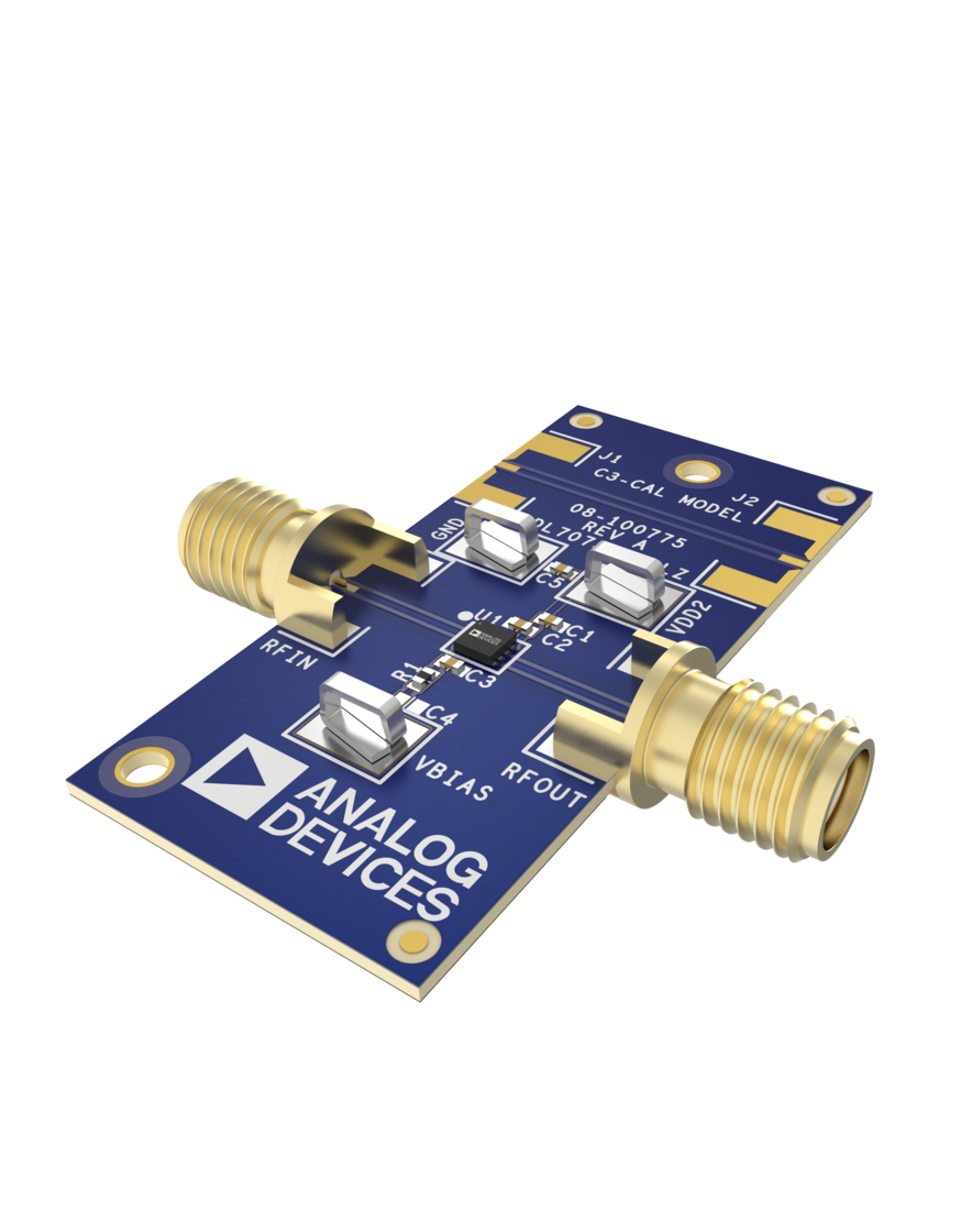
The ADL7075-EVALZ is a 4-layer printed circuit board (PCB) fabricated from 10mil thick, Rogers 4350B, and copper clad.

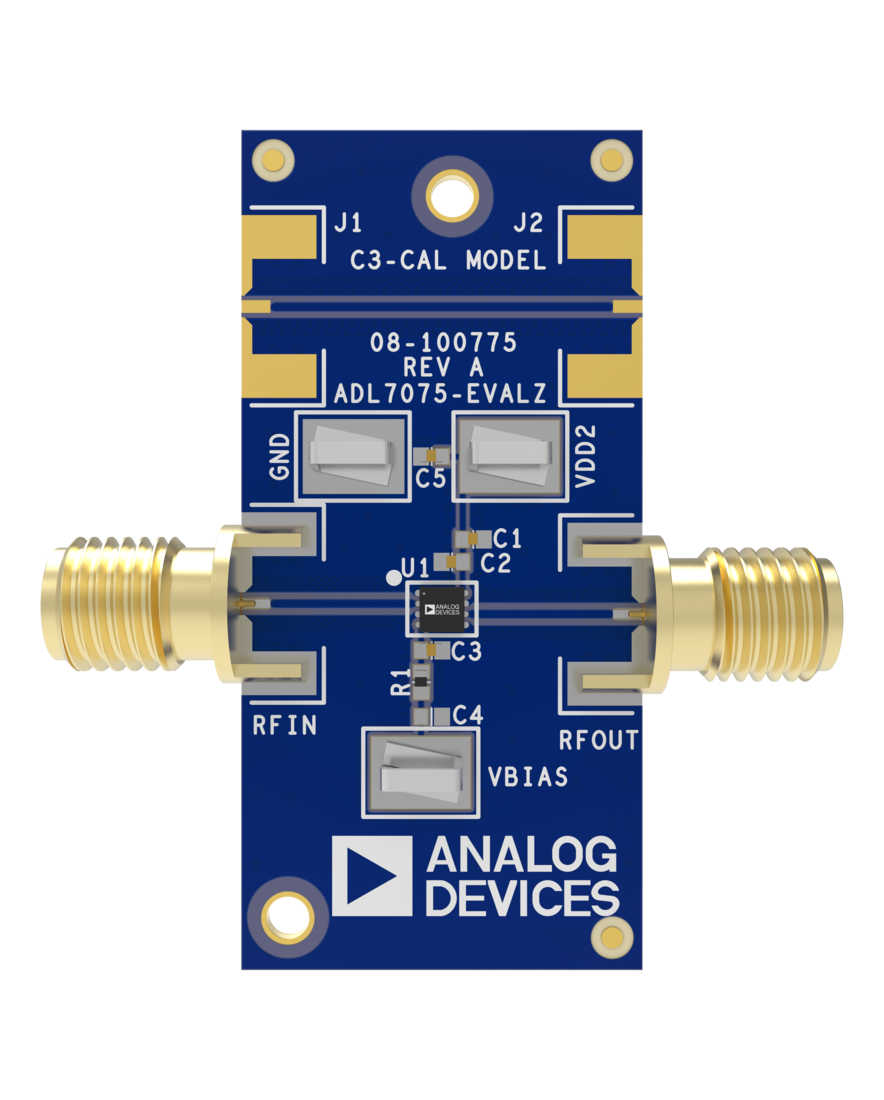
The RFIN and RFOUT ports on the ADL7075-EVALZ are populated with 2.9mm, female coaxial connectors, and the corresponding RF traces have a 50Ω characteristic impedance. The ADL7075-EVALZ is populated with components suitable for use over the entire −55°C to +125°C operating temperature range.

To calibrate board trace losses, a through calibration path, THRUCAL, is provided between the J1 and J2 connectors. J1 and J2 must be populated with RF connectors to use the through calibration path. For the through calibration path performance, see Figure 4 and Table 1.

Access the ADL7075-EVALZ ground path and the VDD pin through the surface-mount technology (SMT) test point connectors, GND, and VDD. A supplementary test point for VBIAS is included for simple access on the RBIAS pin (for the test point locations, see Figure 6).

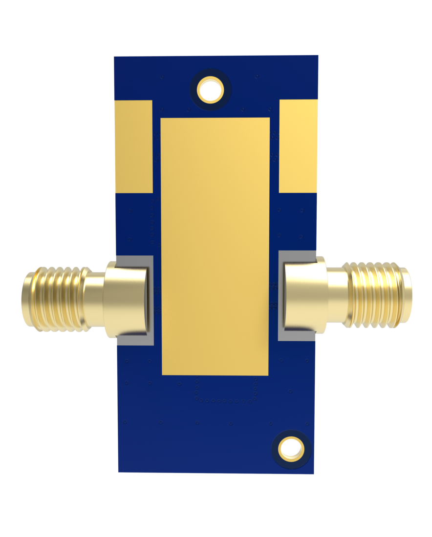
The RF traces on the ADL7075-EVALZ are 50Ω, grounded, coplanar waveguide. The package ground leads and the exposed pads connect directly to the ground plane. Multiple vias connect the top and bottom ground planes with particular focus on the area directly beneath the ground paddle to provide adequate electrical conduction and thermal conduction.

The power-supply decoupling capacitors on the ADL7075-EVALZ represent the configuration used to characterize and qualify the device.

Full specifications on the ADL7075 are available in the ADL7075 data sheet available from Analog Devices, Inc., and must be consulted with this user guide when using the ADL7075-EVALZ evaluation board.

EVAL-ADL7075
Evaluating the ADL7075 100MHz to 31GHz, High Survivability, Low Noise Amplifier
ADL7075-EVALZ Top Angle Evaluation Board ADL7075-EVALZ Top Evaluation Board ADL7075-EVALZ Bottom Evaluation Board

最新评论

需要发起讨论吗? 没有关于 ADL7075的相关讨论?是否需要发起讨论?

在EngineerZone®上发起讨论

近期浏览