ADTR1101
ADTR1101
新規設計に推奨8GHz~12GHz、5W、フロント・エンドIC
- 製品モデル
- 2
- 1Ku当たりの価格
- 価格は未定
Viewing:
製品情報
- 8.0GHz~12GHzで動作
- 送信状態におけるPOUT:37dBm(代表値)(8.5GHz~11.5GHz時)
- 送信状態における小信号ゲイン:35dB(代表値)(8.5GHz~11.5GHz時)
- 受信状態における小信号ゲイン:23dB(代表値)(8.0GHz~10.5GHz時)
- 電力検出用の結合されたパワー・アンプ出力
- 送信経路にRFパワー・ディテクタを内蔵
- 受信経路にリミッタを内蔵
ADTR1101は、パワー・アンプ、低ノイズ・アンプ(LNA)、反射型単極双投(SPDT)スイッチを内蔵した8.0GHz~12GHzの小型フロント・エンドICです。これらの内蔵機能により、このデバイスはフェーズド・アレイ・アンテナやレーダー・アプリケーションに最適なデバイスとなっています。このフロント・エンドICは、8.5GHz~11.5GHzの送信状態で37dBmの出力電力(POUT)と35dBの小信号ゲインを提供し、8.0GHz~10.5GHzの受信状態で23dBの小信号ゲインを提供します。このデバイスは、電力検出用にディレクショナル・カプラとアナログ電圧出力を備えています。更に、ADTR1101にはLNAへの電力を制限する統合リミッタも内蔵されており、RF入出力(I/O)は内部で50Ωに整合されています。
アプリケーション
- フェーズド・アレイ・アンテナ
- 防衛用レーダー
- 気象観測レーダー
- 通信リンク
- 航海用レーダー
ドキュメント
ビデオ 1

| 製品モデル | ピン/パッケージ図 | 資料 | CADシンボル、フットプリント、および3Dモデル |
|---|---|---|---|
| ADTR1101ACCZ | 24-Lead LGA (5mm x 5mm x 1.13mm w/ EP) | ||
| ADTR1101ACCZ-R7 | 24-Lead LGA (5mm x 5mm x 1.13mm w/ EP) |
ソフトウェア・リソース
必要なソフトウェア/ドライバが見つかりませんか?
ドライバ/ソフトウェアをリクエストツールおよびシミュレーション
Sパラメータ 1
評価用キット
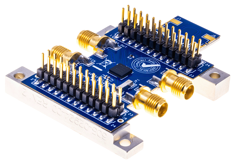
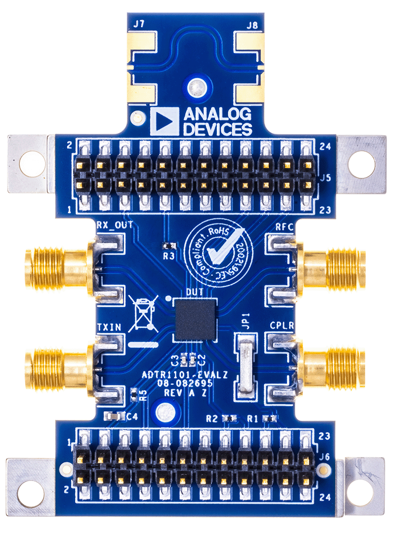
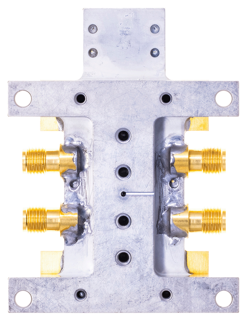
ADTR1101(8GHz~12GHz、5W、フロント・エンドIC)の性能評価