
LTC2975

LTC2975
RECOMMENDED FOR NEW DESIGNS4-Channel PMBus Power System Manager Featuring Accurate Input Current and Energy Measurement
- Part Models
- 8
- 1ku List Price
- Starting From $14.52
Viewing:
Overview
- Sequence, Trim, Margin and Supervise Four Power Supplies
- Manage Faults, Monitor Telemetry and Create Fault Logs
- PMBus™ Compliant Command Set
- Supported by LTpowerPlay® GUI
- Margin or Trim Supplies to Within 0.25% of Target
- Monitor Input Current (±1%) and Accumulate Energy
- Fast OV/UV and OC Supervisors Per Channel
- Coordinate Sequencing and Fault Management Across Multiple LTC PSM Devices
- Automatic Fault Logging to Internal EEPROM
- Operate Autonomously Without Additional Software
- External Temperature and Input Voltage Supervisors
- Accurate Monitoring of Four Output Voltages, Four Output Currents, Four External Temperatures, Input Voltage and Current, and Internal Die Temperature
- Can Be Powered from 3.3V, or 4.5V to 15V
- Pin-Compatible to the LTC2974
- Available in 64-Lead 9mm × 9mm QFN Package and in 63-Lead 6.25mm × 7.5mm BGA Package
- AEC-Q100 Qualified for Automotive Applications
The LTC2975 is a 4-channel Power System Manager used to sequence, trim (servo), margin, supervise, manage faults, provide telemetry and create fault logs. PMBus commands support power supply sequencing, precision point-of-load voltage adjustment and margining. DACs use a proprietary soft-connect algorithm to minimize supply disturbances. Supervisory functions include over and under current, voltage and temperature threshold limits for four power supply output channels as well as over and under voltage threshold limits for a single power supply input channel. Programmable fault responses can disable the power supplies with optional retry after a fault is detected. Faults that disable a power supply can automatically trigger black box EEPROM storage of fault status and associated telemetry. An internal 16-bit ADC monitors four output voltages, four output currents, four external temperatures, input voltage and current, and die temperature. Input power, energy, and output power is also calculated. A programmable watchdog timer monitors microprocessor activity for a stalled condition and resets the microprocessor if necessary. A single wire bus synchronizes power supplies across multiple ADI Power System Management (PSM) devices. Configuration EEPROM with ECC supports autonomous operation without additional software.
APPLICATIONS
- Computers and Network Servers
- Industrial Test and Measurement
- High Reliability Systems
- Video and Medical Imaging
Documentation
Data Sheet 1
User Guide 5
Application Note 6
Design Note 1
Technical Articles 3
Informational 1
Product Information 1
Video 1

Product Selector Card 2
Device Drivers 1
Analog Dialogue 2
Webcast 1
ADI has always placed the highest emphasis on delivering products that meet the maximum levels of quality and reliability. We achieve this by incorporating quality and reliability checks in every scope of product and process design, and in the manufacturing process as well. "Zero defects" for shipped products is always our goal. View our quality and reliability program and certifications for more information.
| Part Model | Pin/Package Drawing | Documentation | CAD Symbols, Footprints, and 3D Models |
|---|---|---|---|
| LTC2975CUP#PBF | 64-Lead QFN (9mm x 9mm x 0.75mm w/ EP) | ||
| LTC2975CUP#TRPBF | 64-Lead QFN (9mm x 9mm x 0.75mm w/ EP) | ||
| LTC2975CY#PBF | 63-Lead BGA (7.5mm x 6.25mm x 1.52mm) | ||
| LTC2975IUP#PBF | 64-Lead QFN (9mm x 9mm x 0.75mm w/ EP) | ||
| LTC2975IUP#TRPBF | 64-Lead QFN (9mm x 9mm x 0.75mm w/ EP) | ||
| LTC2975IUP#WPBF | 64-Lead QFN (9mm x 9mm x 0.75mm w/ EP) | ||
| LTC2975IUP#WTRPBF | 64-Lead QFN (9mm x 9mm x 0.75mm w/ EP) | ||
| LTC2975IY#PBF | 63-Lead BGA (7.5mm x 6.25mm x 1.52mm) |
| Part Models | Product Lifecycle | PCN |
|---|---|---|
|
Apr 29, 2019 - 19_0085 Notification of Change to LTC2975 |
||
| LTC2975CUP#PBF | PRODUCTION | |
| LTC2975CUP#TRPBF | PRODUCTION | |
| LTC2975IUP#PBF | PRODUCTION | |
| LTC2975IUP#TRPBF | PRODUCTION | |
|
Jul 21, 2021 - 21_0159 Ink Mark to Laser Mark Conversion for µModule |
||
| LTC2975CY#PBF | PRODUCTION | |
| LTC2975IY#PBF | PRODUCTION | |
This is the most up-to-date revision of the Data Sheet.
Software Resources
Device Drivers 1
Evaluation Software 0
Can't find the software or driver you need?
Hardware Ecosystem
| Parts | Product Life Cycle | Description |
|---|---|---|
| Power System Management (PSM) & Sequencers 2 | ||
| LTC2974 | RECOMMENDED FOR NEW DESIGNS | 4-Channel PMBus Power System Manager Featuring Accurate Output Current Measurement |
| LTC2977 | RECOMMENDED FOR NEW DESIGNS | 8-Channel PMBus Power System Manager Featuring Accurate Output Voltage Measurement |
Tools & Simulations
Linduino 4
Linduino is Analog Devices’ Arduino compatible system for developing and distributing firmware libraries and example code for our integrated circuits. Each Linduino-supported product includes an example main program, defined in the LTSketchbook/Part Number folder and driver code, defined in the LTSketchbook/libraries folder.
Linduino code repository on GitHub and instructions on how to use the code.
Evaluation Kits
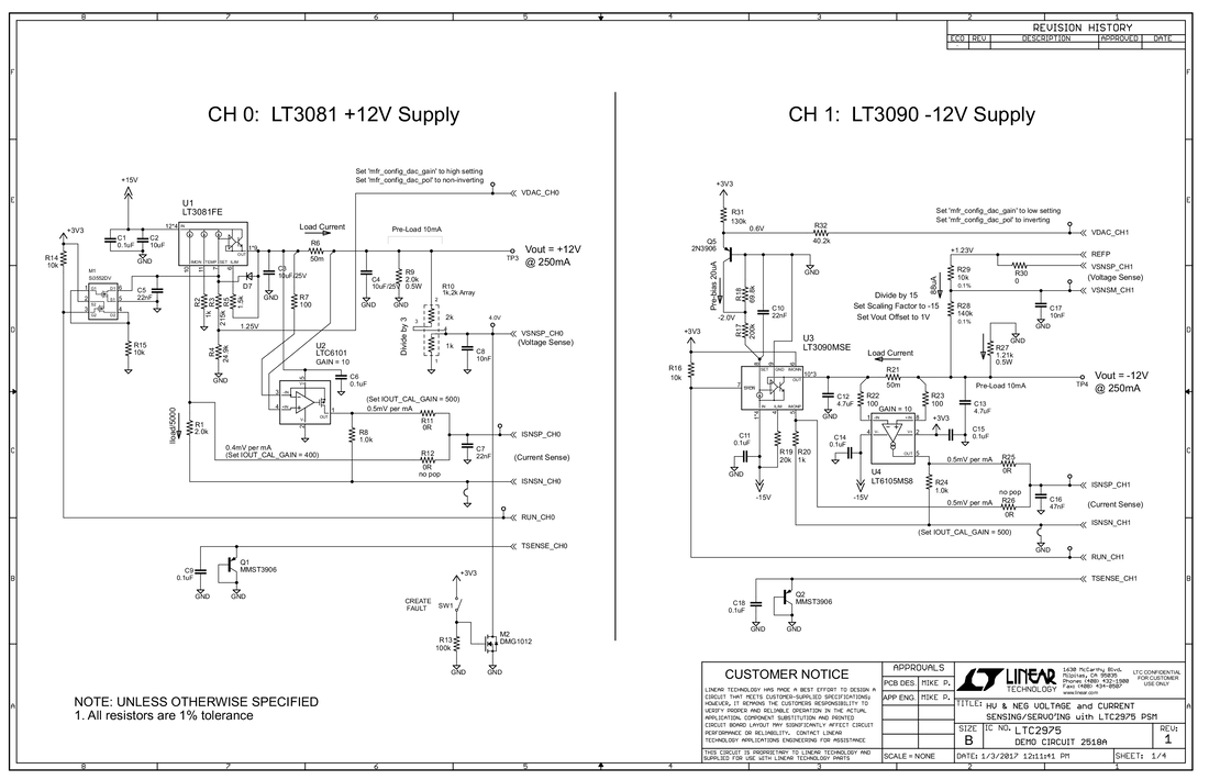
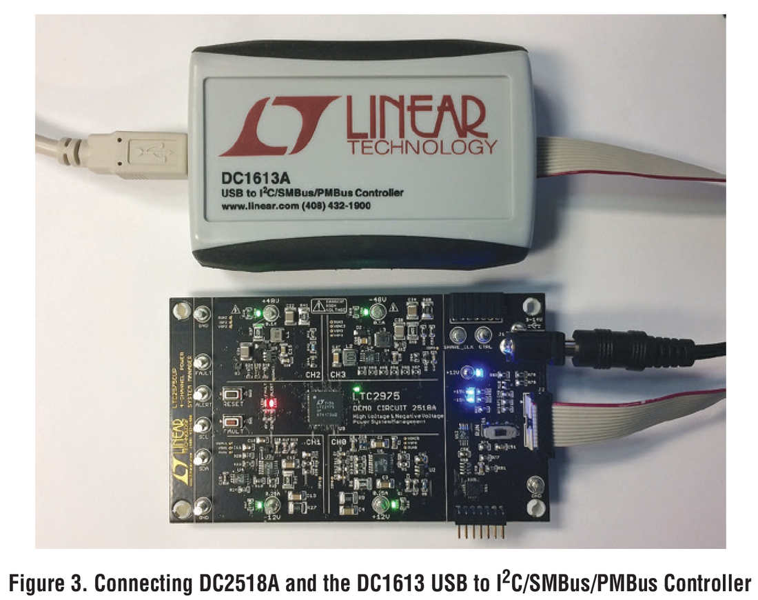
LTC2975 Demo Board: ±12V, ±48V Power Supply Management [requires DC1613]
Resources
Software
LTC2975 Demo Board: ±12V, ±48V Power Supply Management [requires DC1613]
Resources
Software
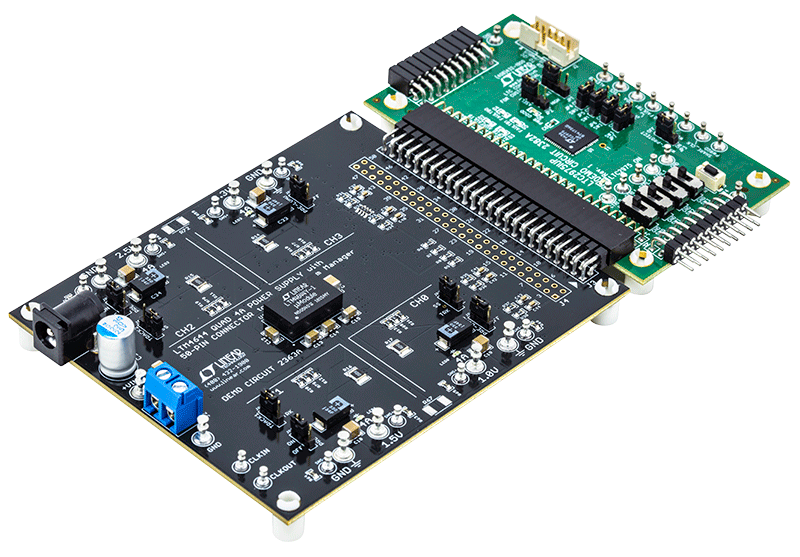
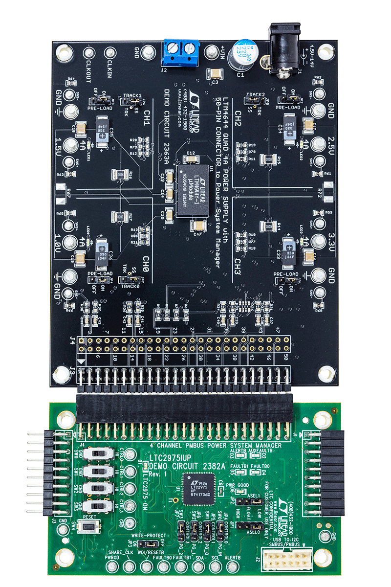
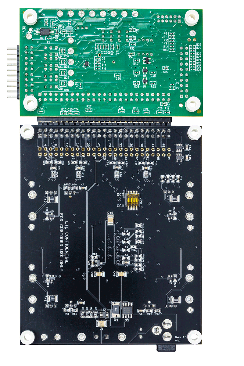
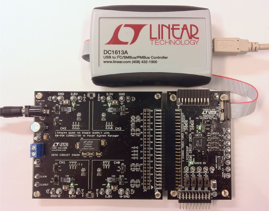
LTC2975 Demo Board Set | LTM4644-1 Quad 4A Power Supply Management (includes DC2382A + DC2363A) [requires DC1613]
Resources
Software
LTC2975 Demo Board Set | LTM4644-1 Quad 4A Power Supply Management (includes DC2382A + DC2363A) [requires DC1613]
Resources
Software
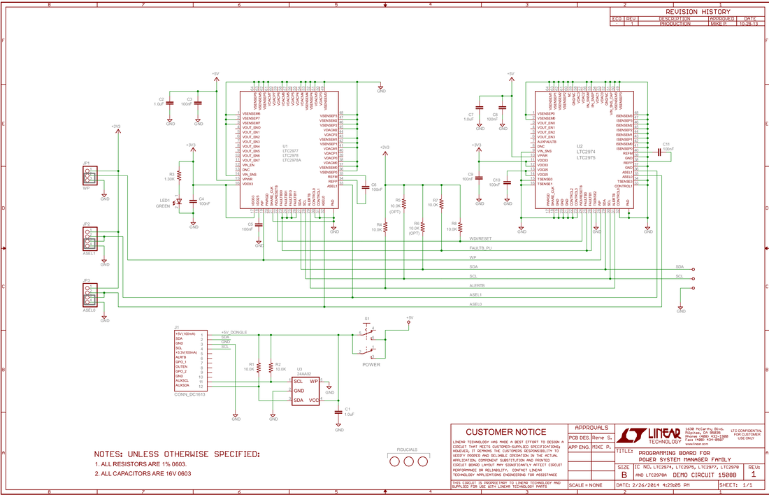
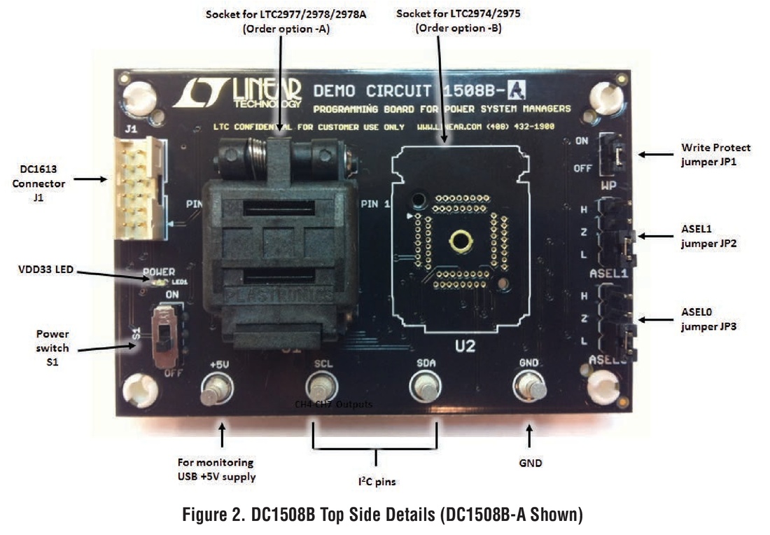
LTC2974, LTC2975 Socketed Programming Board (Requires DC1613)
Resources
Software
LTC2974, LTC2975 Socketed Programming Board (Requires DC1613)
Resources
Software
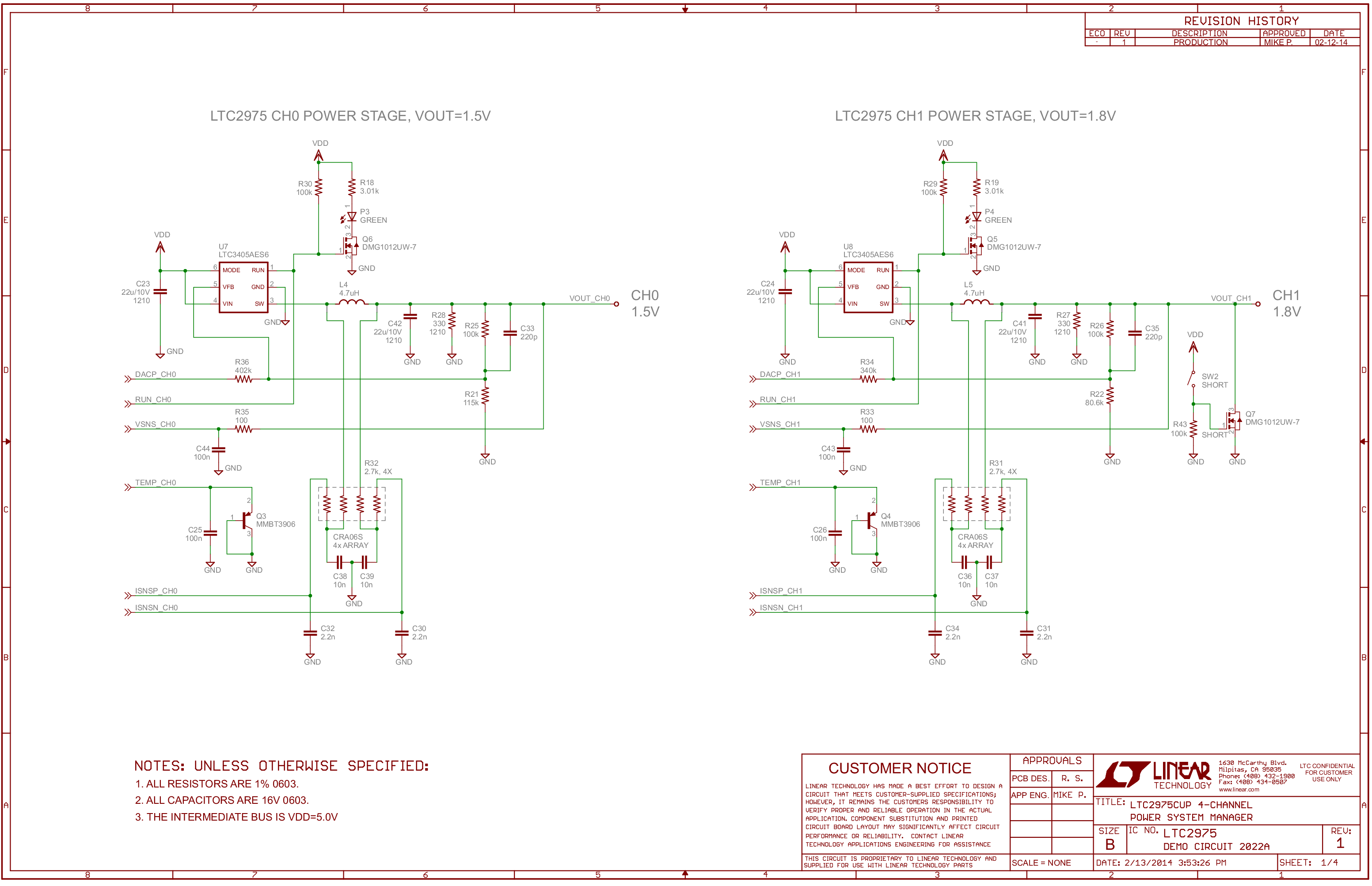
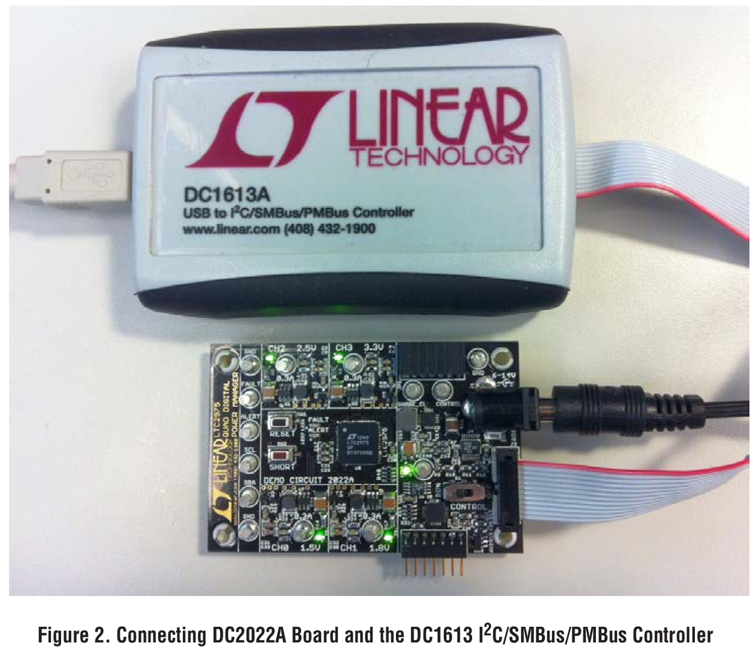
LTC2975 Demo Board: 4 Power Supply Manager with Input Energy Monitoring [Requires DC1613]
Resources
Software
LTC2975 Demo Board: 4 Power Supply Manager with Input Energy Monitoring [Requires DC1613]
Resources
Software
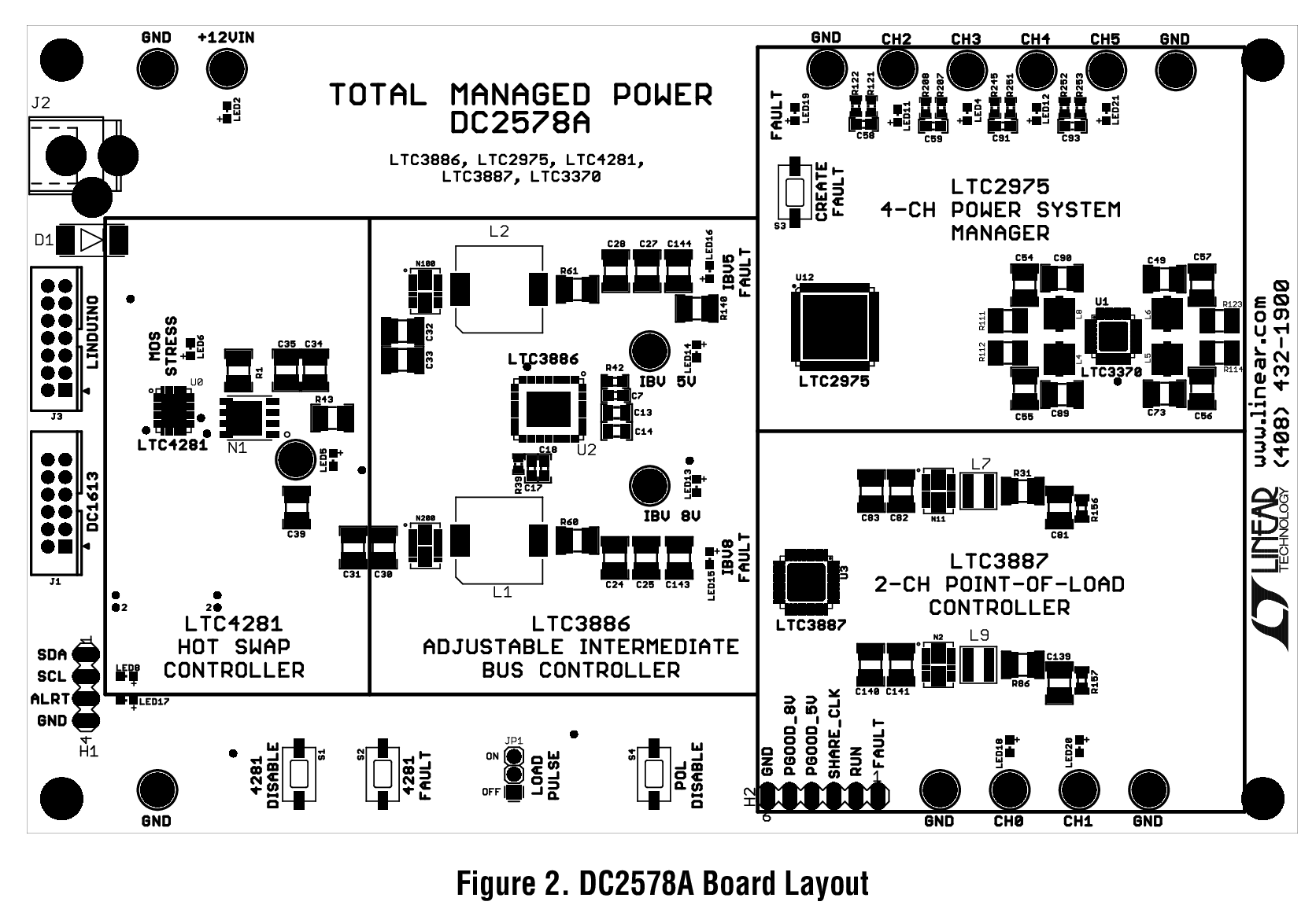
Total Power Management: Hot Swap, Intermediate Bus Voltage, Point-of-Load (Featuring LTC4281, LTC3886, LTC3887, LTC2975) [Requires DC1613]
Resources
Software
Total Power Management: Hot Swap, Intermediate Bus Voltage, Point-of-Load (Featuring LTC4281, LTC3886, LTC3887, LTC2975) [Requires DC1613]