
Position Sensing Solutions
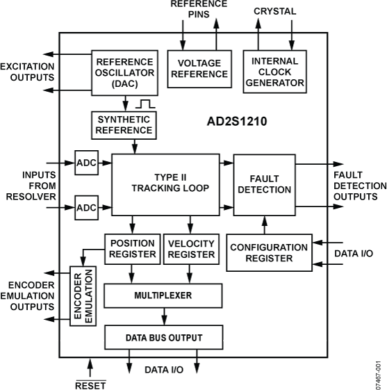
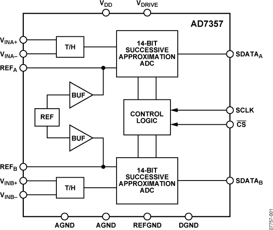
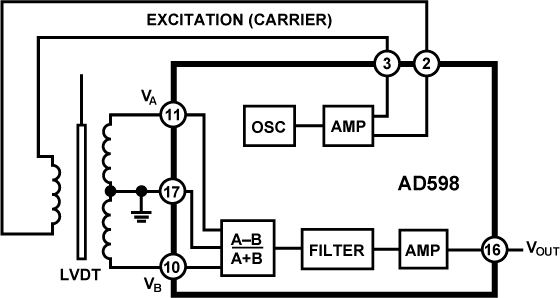
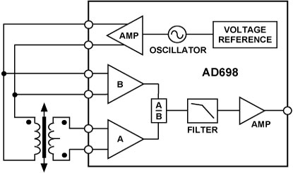
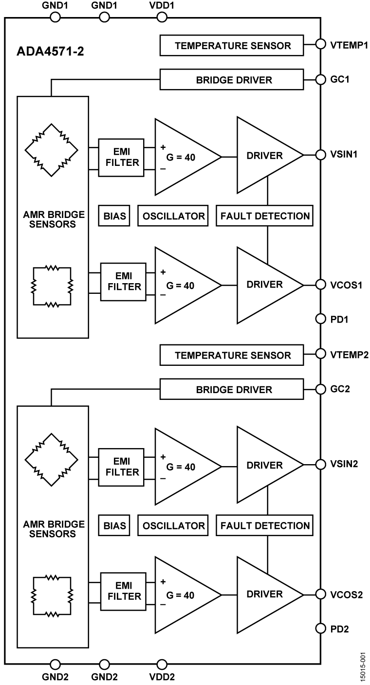
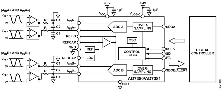
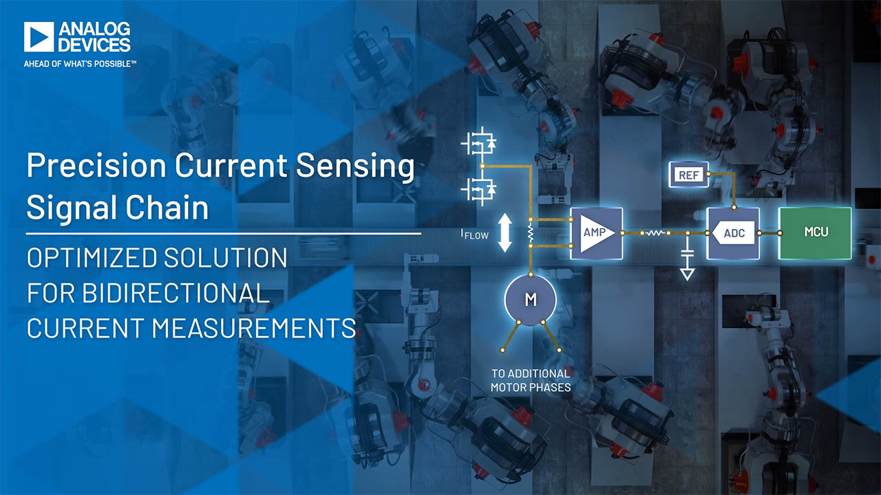
Position sensors are widely used in closed-loop mechanical control systems across a wide variety of industries including automotive, industrial automation, process control, and military and aerospace. Analog Devices provides signal chain solutions for most common, high-precision position sensors such as optical encoders, resolvers, and LVDTs and magnetic sensors (AMR, TMR, Hall). Our signal chain solutions ensure that position measurement is done accurately, optimizing overall solution size and power consumption.
Value and Benefits
- Accurate Position Sensing: Enable precise, intelligent mechanical system performance across diverse applications.
- Accelerated Design: Signal chain and reference designs speed development of position sensing systems.
- Sensor Versatility: Support optical encoders, resolvers, LVDTs, and magnetic sensors.
- Optimized Efficiency: Minimize solution size and power consumption.
Solution Resources
Hardware Products
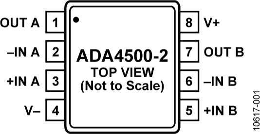
10 MHz, 14.5 nV/√Hz, Rail-to-Rail I/O, Zero Input Crossover Distortion Amplifier
10 MHz, 14.5 nV/√Hz, Rail-to-Rail I/O, Zero Input Crossover Distortion Amplifier
Interactive Signal Chains


Reference Designs

Trainings and Tutorials


{{modalTitle}}
{{modalDescription}}
{{dropdownTitle}}
- {{defaultSelectedText}} {{#each projectNames}}
- {{name}} {{/each}} {{#if newProjectText}}
-
 {{newProjectText}}
{{/if}}
{{newProjectText}}
{{/if}}
{{newProjectTitle}}
{{projectNameErrorText}}