ADPA1120
新規設計に推奨4.5W(36.5dBm)、8GHz~12GHz、窒化ガリウム(GaN)パワー・アンプ
- 製品モデル
- 2
- 1Ku当たりの価格
- 最低価格:$109.92
製品情報
- 内部整合およびACカップリングされた4.5W窒化ガリウム(GaN)パワー・アンプ
- 温度補償RFパワー・ディテクタを内蔵
- POUT:9.5GHz~11.5GHz、PIN = 1dBmで36.5dBm(代表値)
- 小シグナル・ゲイン:9.5GHz~11.5GHzで38.5dB(代表値)
- パワー・ゲイン:9.5GHz~11.5GHz、PIN = 1dBmで35.5dB(代表値)
- PAE:9.5GHz~11.5GHz、PIN = 1dBmで47%(代表値)
- 電源電圧:20V(50mA、10%のデューティ・サイクル)
- 32ピン、5mm × 5mm、LFCSP
ADPA1120は8GHz~12GHzのパワー・アンプで、周波数範囲が9.5GHz~11.5GHz、入力電力(PIN)が1dBmの場合に、36.5dBmの飽和出力電力(POUT)、47%の電力付加効率(PAE)、35.5dBのパワーゲイン(それぞれ代表値)を実現します。RF入力とRF出力は内部整合され、AC結合されています。VDD1-2、VDD3、VDD4の各ピンに、20Vのドレイン・バイアス電圧が印加されます。ドレイン電流は、VGG1-2ピンに負電圧を印加することで設定されます。
ADPA1120は窒化ガリウム(GaN)プロセスで製造され、32ピン、5mm × 5mmのリード・フレーム・チップ・スケール・パッケージ[LFCSP]に収められており、−40°C~+85°Cで動作するように仕様規定されています。
アプリケーション
- 気象観測レーダー
- 航海用レーダー
- 防衛用レーダー
ドキュメント
データシート 2
ユーザ・ガイド 1
| 製品モデル | ピン/パッケージ図 | 資料 | CADシンボル、フットプリント、および3Dモデル |
|---|---|---|---|
| ADPA1120ACPZN | 32-Lead LFCSP (5mm x 5mm x 0.75mm w/ EP) | ||
| ADPA1120ACPZN-R7 | 32-Lead LFCSP (5mm x 5mm x 0.75mm w/ EP) |
これは最新改訂バージョンのデータシートです。
ソフトウェア・リソース
必要なソフトウェア/ドライバが見つかりませんか?
ドライバ/ソフトウェアをリクエストツールおよびシミュレーション
Sパラメータ 1
評価用キット
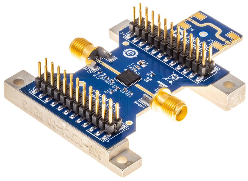
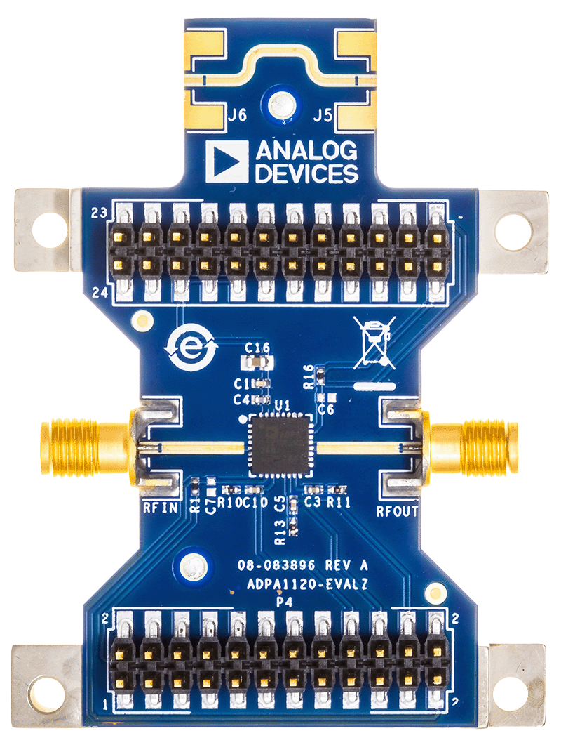
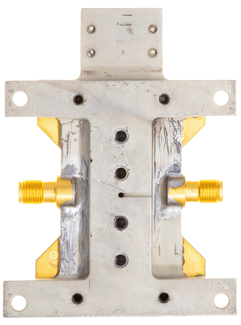
ADPA1120(4.5W(36.5dBm)、8GHz~12GHz、窒化ガリウム(GaN)パワー・アンプ)の性能評価
資料
最新のディスカッション
ADPA1120に関するディスカッションはまだありません。意見を投稿しますか?
EngineerZone®でディスカッションを始める