Overview
Design Resources
Design & Integration File
- Schematic
- Bill of Materials
- Gerber Files
- Allegro Layout Files
- Assembly Files
Evaluation Hardware
Part Numbers with "Z" indicate RoHS Compliance. Boards checked are needed to evaluate this circuit.
- EVAL-CN0533-EBZ ($88.28) 4-20mA Wideband MEMs Vibration Sensor
Features & Benefits
- 10kHz MEMs Vibration Sensor
- 4mA to 20mA Industrial Output
- Compatible with the EVAL-XLMOUNT1 Mounting Cube
Product Categories
Markets and Technologies
Parts Used
Documentation & Resources
Circuit Function & Benefits
Condition-based monitoring (CbM) is one form of predictive maintenance that uses various sensors to assess the operating status of equipment over time. The collected sensor data is used to establish baseline trends, which then help diagnose or even predict failure. Utilizing CbM, maintenance is performed when needed as opposed to the conventional periodic preventive maintenance model, saving both time and cost.
Vibration monitoring is a common type of CbM measurement. Changes in vibration trends are often indicative of wear or other failure modes. To measure vibration data, high bandwidth (10 kHz and more), ultralow noise (100 μg/√Hz or lower) MEMS accelerometers are a cost effective and reliable choice.
While some applications place the accelerometer close to the supporting circuitry (either on the same board or off board through a short cable), others require the accelerometer to be some distance away, which limits connectivity options. MEMS accelerometer outputs are typically analog voltage and/or digital (typically, serial peripheral interface (SPI) or I2C), none of which are well suited to driving long cables. It is possible to convert to a high speed digital interface such as USB, low voltage digital signaling (LVDS), or Ethernet. However, the additional power, size, and cost are not practical.
In contrast, analog current loop data transmission, such as the 4 mA to 20 mA industry standard, offers good noise immunity, robustness in electromagnetic interference (EMI) prone environments, high bandwidth, and up to a 20 meter long wire data transmission, all while keeping the number of devices in the circuit board to a few components. Furthermore, the 4 mA to 20 mA signaling standard is supported by nearly all legacy industrial data acquisition (DAQ) systems and can be adapted simply to the modern, Industry 4.0 smart sensor node.

Circuit Description
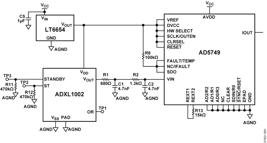
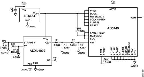
The circuit shown in Figure 1 is a simplified schematic of a MEMS accelerometer vibration sensing solution whose voltage output is converted into a 4 mA to 20 mA analog signal.
4 mA to 20 mA Current Loop and Interface
The 4 mA to 20 mA current loop has been an industry analog signaling standard since the 1950s. The main advantage of this signal standard is that virtually no attenuation over long cables exists, which results in more robustness in EMI prone environments, such as industrial and factory settings. On the contrary, if a voltage output is used, there is voltage drop over long cables (greater than 10 meters) due to the cable resistance, resulting in loss of sensor data and incorrect sensor readings.
The reference design shown in Figure 1 consists of a single axis ADXL1002 MEMS accelerometer, whose analog voltage output is converted to the 4 mA to 20 mA signaling standard by using an AD5749 voltage to current converter. The AD5749 input (VIN) swings from 0 V to 4.096 V, and the ADXL1002 analog output voltage (VOUT) swings from 0 V to VDD, thus VDD must be set to 4.096 V. Therefore, the LT6654AMPS6-4.096 was chosen to supply the 4.096 V with a 10 ppm/°C temperature stability over the −55°C to 125°C temperature range. A 2-pole RC low-pass filter with a −3 dB bandwidth of 36 kHz is placed between VOUT and VIN. This filter limits broadband noise and attenuates the noise component at 200 kHz from the internal clock of the ADXL1002, which may alias in-band depending on the sample rate and filtering characteristics of the DAQ circuitry of the application.
The AD5749 directly translates the ADXL1002 voltage output signal to a 4 mA to 20 mA current output, with minimal impact on the printed circuit board (PCB) footprint and offers up to a 50 kHz bandwidth and good noise immunity.
Many of 4 mA to 20 mA drivers in the market consist of current output, digital-to-analog converters (DACs) and require SPI or I2C external controllers. The AD5749 4 mA to 20 mA driver has the additional advantage of a standalone operation mode (hardware mode).
In hardware mode, set the HW_SELECT pin high. The R0 to R3 and RSET pins are all tied low to set the AD5749 output range to 4 mA to 20 mA, which means no external micro-controller is required to configure the AD5749 output range. To improve the stability of the output current over temperature, connect an external low drift resistor between the REXT1 and REXT2 pins.
On the DAQ front-end circuitry (not included), only one current to voltage (I-V) conversion amplifier is required. The transimpedance (I-V resistance) must be set according to the input range of the DAQ front-end circuitry.
Figure 2 shows an example of the circuit current output (IOUT) when shaken manually (black line). The 0 g level corresponds to the IOUT midrange, which is 12 mA for the 4 mA to 20 mA configuration. The full-scale range (FSR) is also highlighted in gray dashed lines for reference.

MEMS Vibration Sensors Advantages
The ADXL1002 MEMS accelerometer has ultralow noise, with a noise spectral density of 25 μg/√Hz and a wideband operation with a 3 dB bandwidth of 11 kHz, and a sensor resonance frequency of 21 kHz. The ADXL1002 provides superior performance in temperature sensitivity, dc to low frequency response, phase response (and thus, group delay), shock tolerance, and recovery, with noise level and bandwidth comparable with a piezoelectric sensor.
The sensor has a linear (within ±0.1% FSR) measurement range of ±50 g, which is large enough to support a wide range of CbM applications. An easy to solder LFCSP makes it simple to integrate the ADXL1002 and surrounding circuitry as opposed to conventional piezoelectric sensors.
The ADXL1002 provides a low cost, high performance sensing solution for CbM applications with superior long-term reliability. These unique features allow for a ubiquitous utilization of the MEMS vibration sensors in CbM solutions and expanding the reach of smart technologies in the push towards Industry 4.0.
Common Variations
Depending on application requirements, the CN0533 circuit can accommodate other single-axis, voltage output MEMS accelerometers, such as the ADXL1001, ADXL1003, ADXL1004, and ADXL1005. Select the low-pass filter cutoff frequency based on the sensor resonance frequency.
Using a 5 V supply for the ADXL1002 and scaling the output to 4.096 V with a precision voltage divider before the AD5749 input allows the circuit to achieve the data sheet spectral noise level of the accelerometer.
Circuit Evaluation & Test
A brief description of how to set up the circuit and mechanical mounting, the methods to read the output, and what to expect is given in the following subsections.
For complete details, see the CN0533 User Guide.
Equipment Needed
The following equipment is needed:
- A 4 mA to 20 mA receiver (for example, National Instruments NI-9203). Note that an accurate and temperature stable resistor along with a voltage DAQ system may also be used instead of a current DAQ. The resistance value must be according to the input voltage range of the DAQ.
- A power supply (12 V to 24 V)
- The EVAL-CN0533-EBZ board
- The EVAL-XLMOUNT1 aluminum mounting block
- A shaker table or vibration source
- Connectors and cables
Getting Started
The basic steps for understanding and recreating the test setup follow:
- Solder three wires to the VCC, IOUT, and GND pads of the EVAL-CN0533-EBZ board.
- Firmly attach the EVAL-XLMOUNT1 to a shaker or vibration platform.
- Mount the EVAL-CN0533-EBZ board to the EVAL-XLMOUNT1 and note the sensitivity direction.
- Connect VCC and GND to the power supply and IOUT and GND to the 4 mA to 20 mA receiver circuit.
- Set the acceleration sensitivity to 128 μA/g on the DAQ or vibration measurement equipment (the sensitivity scale of the ADXL1002 may slightly vary from part to part, and the ADXL1002 can be simply calibrated with the gravity field or other reference sensors).
Power Supply Configuration
The circuit voltage supply range is 12 V to 55 V, and the maximum current consumption is 24 mA typically.
Tests
To verify performance of the circuit for vibration measurement applications, the circuit was tested in the Analog Devices, Inc., vibration lab. Because the vibration DAQ system inputs are all voltage inputs, a 50 Ω temperature stable and high precision resistor was used to close the current loop, and the circuit output was measured indirectly as a voltage drop in the resistor. The circuit is characterized for its frequency response, noise spectral density, and shock and group delay. The details and results of each test follows.
Frequency Response Measurements
The EVAL-CN0533-EBZ is attached to an aluminum block mounting interface (EVAL-XLMOUNT1) and attached to a shaker table, as shown in Figure 3. The shaker table generates a controlled mechanical vibration from 100 Hz to 30 kHz, with a fixed 2 g acceleration amplitude. The circuit output and the vibration reference (in this case, a laser doppler vibrometer) are then recorded. The plotted frequency response is shown in Figure 4, which is consistent with the transfer function of the ADXL1002.


In this and any other high frequency vibration tests, mechanical signal path integrity is important. In other words, from the source to the sensor, there must be no attenuation (due to damping) nor amplification (due to resonance) of the vibration signal. In this example, for instance, the aluminum block (EVAL-XLMOUNT1), four screw mounts, and a thick PCB guarantees a flat mechanical response for the frequency range of interest.
Noise Spectral Density
Noise density characterization at different temperature levels ranging from −40°C to +105°C for the sensor is shown in Figure 5. The results show that noise density variations over temperature range are slightly more than the ADXL1002 sensor IC. The reason for the elevated noise density is that the supply voltage of the ADXL1002 is 4.096 V instead of 5 V. This reduction in the supply increases the spectral noise density by about 20%. The 4.096 V power supply was chosen as a common source for both the voltage reference (VREF) on the AD5749 and output voltage (VOUT) on the ADXL1002 so that there is no conversion error due to mismatch between the two voltage levels.

Response to Sine Wave Vibration
Figure 6 illustrates a sample set of data taken with the EVAL-CN0533-EBZ stimulated by a 10 kHz sine vibration with 10 g amplitude (the red data). The reference sensor shown in this test (the blue data shown in Figure 6) is an acceleration measurement by a laser doppler vibrometer. The EVAL-CN0533-EBZ shows a delay of approximately 20 μs relative to the vibrometer.

Shock Test
The circuit is also tested with a shock profile (see Figure 7). The shock peak acceleration is 10 g, the width is 500 μs, and the shape is a square wave. Note that ringing of the output is expected because the ADXL1002 MEMS sensor can be modeled with an underdamped second-order system.
The reference sensor in this case is a piezoelectric sensor (Model 353C23) with a resonance frequency and characterized group delay of 4 μs. Note that there is ~25 μs phase difference between the reference sensor output and the output of the ADXL1002. Therefore, the overall group delay of the circuit is approximately 21 μs.


