

Operational Amplifiers (Op Amps)
Subcategories
Products in Category
Related Resources






Related Tools
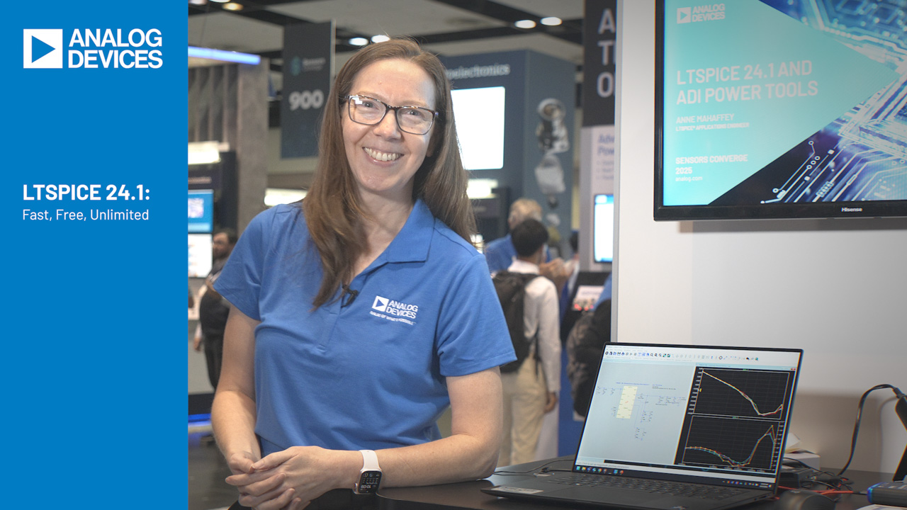
LTspice® is a high performance SPICE simulation software, schematic capture and waveform viewer with enhancements and models for easing the simulation of analog circuits. Included in the download of LTspice are macromodels for a majority of Analog Devices switching regulators, amplifiers, as well as a library of devices for general circuit simulation.
LTspice® is a high performance SPICE simulation software, schematic capture and waveform viewer with enhancements and models for easing the simulation of analog circuits. Included in the download of LTspice are macromodels for a majority of Analog Devices switching regulators, amplifiers, as well as a library of devices for general circuit simulation.
The LTpowerCAD® program is a complete power supply design tool that can significantly ease of power supply design. It provides recommendations for component values and performance estimates specific to the user’s application with Analog Devices power products. Also included within the LTpowerCAD platform is LTpowerPlanner®, a system-level power architecture design tool.
Use Photodiode Wizard to design a transimpedance amplifier circuit to interface with a photodiode. Select a photodiode from the library included in the tool, or enter custom photodiode specifications. Quickly observe tradeoffs between Bandwidth, Peaking (Q), and ENOB/SNR. Modify circuit parameters, and immediately see results in plots for pulse response, frequency response, and noise gain.
Analog Filter Wizard Design Tool


Analog Filter Wizard Design Tool
FAQs
What are Operational Amplifiers (Op Amps)?
Operational amplifiers (op amps) are high-gain voltage amplifiers with differential inputs and a single output. They serve as fundamental building blocks for amplification, filtering, signal conditioning, integration, and differentiation. Available in precision, high-speed, and power variants, op amps are essential in sensor interfaces, data acquisition systems, and analog control loops.
How do I design a basic inverting amplifier using an op amp?
To design a basic inverting amplifier, connect the input signal through resistor Rin to the inverting input, with feedback resistor Rf from output to that node; gain is −Rf/Rin. Ground the non-inverting input only for suitable dual supplies or ground-centered signals. On single supplies, use a reference voltage. Check headroom, resistor noise, bias-current error, bandwidth, stability, load drive, and decoupling.
How does an op amp function as an integrator in electronic circuits?
An op amp integrator uses input resistor R and feedback capacitor C, ideally giving VOUT = −(1/RC)∫VIN dt. A parallel resistor limits DC gain and sets the low-frequency cutoff. Check initial conditions, output headroom, offset, and bias-current errors. For a practical implementation, see EVAL-KW4101Z and verify the amplifier’s operating limits.
Can you recommend ways to improve the slew rate of an op amp?
To improve op amp slew rate, select a device with a higher slew rate specification suited to your signal frequency and amplitude requirements. Reduce output voltage swing and minimize load capacitance. Check large-signal bandwidth, output-current demand, compensation, minimum stable gain, and stability. Avoiding unity-gain configurations does not inherently improve slew rate, and external circuitry cannot increase the intrinsic slew rate.
Are there any step-by-step guides for troubleshooting op amp circuits?
When troubleshooting op amp circuits, verify power supply voltages and decoupling capacitor placement. Use an oscilloscope to check for output oscillations. First consult the datasheet for operating limits, then check pinout, enable state, grounding, feedback, output load, saturation recovery, capacitive loading, soldering, layout, and probing. Use product-specific notes; Analog Filter Wizard is a filter-design tool, not a general diagnostic guide.

{{modalTitle}}

{{modalDescription}}
{{dropdownTitle}}

- {{defaultSelectedText}} {{#each projectNames}}
- {{name}} {{/each}} {{#if newProjectText}}
-
 {{newProjectText}}
{{/if}}
{{newProjectTitle}}

{{projectNameErrorText}}