Overview
Design Resources
Design & Integration File
- Schematic
- Bill of Materials
- Allegro Layout File
- Gerber Files
- UL-217 Test Documentation
Evaluation Hardware
Part Numbers with "Z" indicate RoHS Compliance. Boards checked are needed to evaluate this circuit.
- ADSW-SMOKEALGO-PRODLIC ($27500.00) ADPD188BI Smoke Detection Algorithm
- ADSW-SMOKEALGO-SUP100 ($22500.00) Paid Support 100hrs
- ADSW-SMOKEALGO-SUP200 ($38500.00) Paid Support 200hrs
- ADSW-SMOKEALGO-SUP50 ($12500.00) Paid Support 50hrs
- ADSW-SMOKEALGO-SUPCUST Paid Custom Support
- ADSW-SMOKEDATA-PRODLIC ($11000.00) ADPD188BI Smoke Detection Dataset
- EVAL-ADICUP3029 ($52.97) Ultra Low Power Arduino Form Factor Compatible Development Board
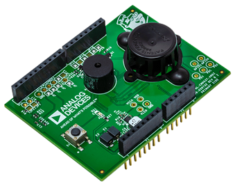
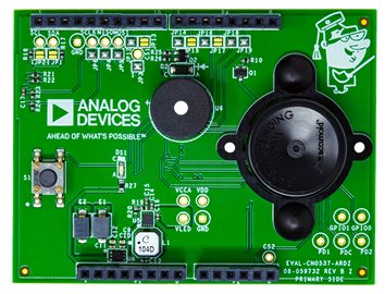
- EVAL-CN0537-ARDZ ($63.56) UL-217 8th Edition Certifiable Reference Design
Device Drivers
Software such as C code and/or FPGA code, used to communicate with component's digital interface.
Features & Benefits
The CN0537 reference design includes a complete data and software offering designed to accelerate smoke/fire detection application development.
The Data (ADSW-SMOKEDATA-PRODLIC) package provides an extensive (1000+) smoke dataset taken at UL-217 certified facilities for those who wish to develop their own algorithm. It includes the CN0537 source code for initialization, calibration, environmental compensation, data pre-processing - but excludes the detection algorithm.
The Algorithm (ADSW-SMOKEALGO-PRODLIC) package includes everything in the Data package and adds a UL certified smoke detection algorithm and associated algorithm project files.
Product Categories
Markets and Technologies
Parts Used
Documentation & Resources
-
CN0537 User Guide7/7/2020WIKI
-
Smoke Detection Solutions Frequently Asked Questions12/17/2020PDF811 K
-
Solutions For Rapid Prototyping: Answering the Needs of Practicing Engineers8/23/2023PDF784 K
-
CN0537: Multistandard Verified Smoke Detector Solution (Rev. A)7/15/2020PDF424 K
Circuit Function & Benefits
This reference design plus related software is designed and tested to meet UL 217/UL 268 and similar smoke/fire detection standards. To address the needs of different customers a number of solution offerings are available which are summarized in the table below. The hardware is Arduino form factor compatible and is designed to accelerate prototyping and the evaluation of the embedded smoke detection algorithm. The hardware is compromised of the EVAL-CN0537-ARDZ reference design which is described the CN0537 circuit note and the supporting EVAL-ADICUP3029 microcontroller board. The Data (ADSW-SMOKEDATA-PRODLIC) package provides an extensive smoke dataset taken at UL certified facilities for those who wish to develop their own algorithm and the CN0537 source code - excluding the detection algorithm. The Algorithm (ADSW-SMOKEALGO-PRODLIC) package includes everything in the Data package and a UL certified smoke detection algorithm with associated algorithm project files.
| Solution Options | Description | Includes |
|
Hardware
EVAL-CN0537-ARDZ |
|
Hardware
Software
Documentation
|
|
Data ADSW-SMOKEDATA-PRODLIC |
Source code and over 1000+ sample fire/smoke datasets to accelerate system development. |
Data
Software
|
|
Algorithm ADSW-SMOKEALGO-PRODLIC |
The algorithm package includes the Intertek Test Results for UL-217, EN-14604, and EN54-7, smoke detection algorithm, associated project files, full source code, and over 1000+ sample fire/smoke datasets to accelerate system development. |
Software
Data
Documentation,/p>
Support
|
Since the 1970s, smoke detectors have become commonplace in commercial and residential buildings. Two basic types of detectors exist today, the ionization type that uses radioactive matter to ionize the air and checks for an electrical imbalance, and the photoelectric type that uses a light source aimed at an angle away from a photodetector and checks for photodetector current caused by the light reflecting from airborne particles to the photodiode. Although a combination solution of both types is recommended, the photoelectric smoke detector is more popular due to its improved reliability in detecting common house fires and faster response times to smoldering fires.
Unfortunately, smoke detector technology and regulations have also remained virtually the same since the 1970s despite the advances in electronics and common household materials through the decades. New revisions in standards, such as ANSI/UL 217 and ANSI/UL 268, published by Underwriters Laboratory (UL), or the NFPA® 72 National Fire Alarm Code, published by the National Fire Protection Agency (NFPA), aim to address this gap by placing more complex requirements on modern smoke detector designs. Other worldwide standards, such as EN 14604, EN 54, and ISO 7240 will likely add similar tests to address this and other concerns in the future, making it more important to have more advanced sensing capabilities.
The goal of these updated standards is to increase safety and decrease the number of fire related deaths by reducing the number of false alarms that are generated from everyday activity. For example, in addition to the traditional fire and smoke sensitivity tests, the 8th edition of UL 217 and the 7th edition of UL 268 now requires that smoke detectors do not produce a false alarm during nuisance events, like cooking. Therefore, modern smoke detectors must be able to distinguish between a cooking nuisance event and a fire event. Traditionally, this goal required a complicated solution with multiple sensor technologies and a level of artificial intelligence. However, the use of the ADPD188BI makes this solution significantly more simple to implement.
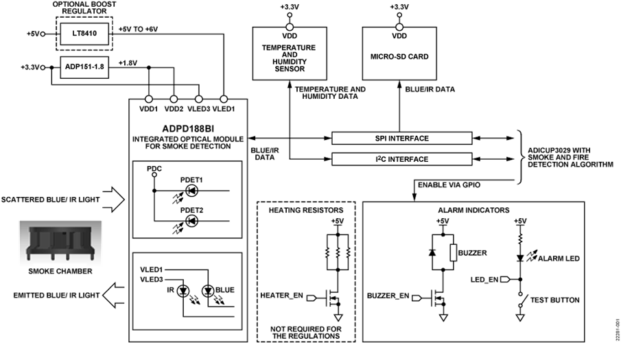
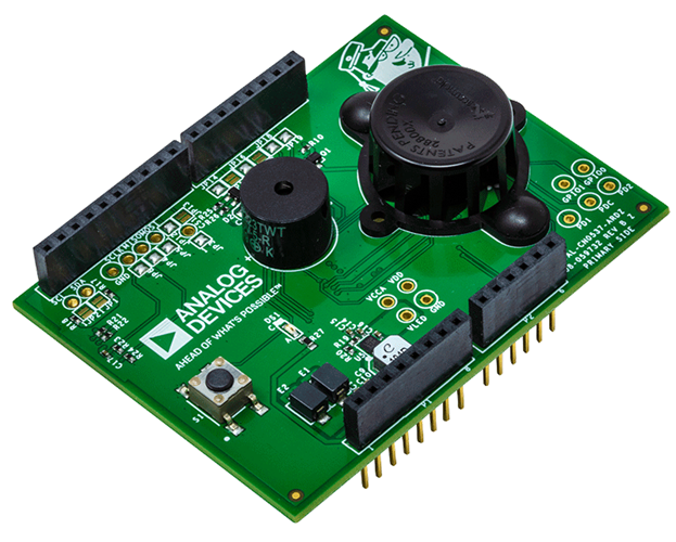
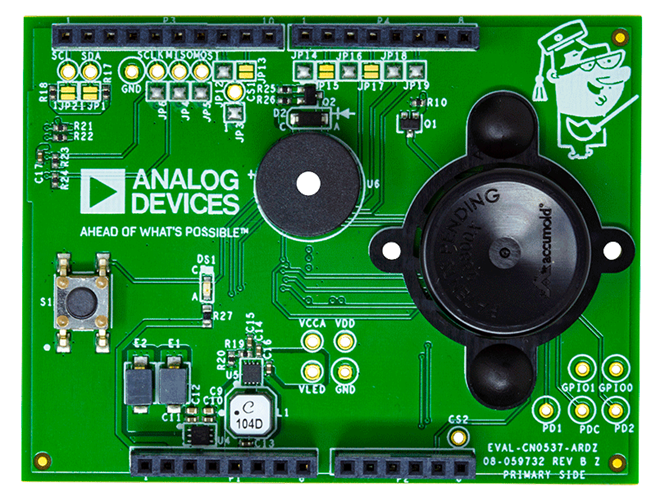
The circuit shown in Figure 1 is a tested and verified smoke detector reference design with an available algorithm and a data set based on the ADPD188BI optical module. For easy and rapid development, the design is made compatible with the Arduino form factor controller platforms. Software and embedded algorithms combined with the hardware can be used to evaluate smoke and fire tests specified in 8th edition of the UL 217 and the 7th edition of the UL 268 standards. Verified algorithms are available for direct use to help deploy the smoke detection solution faster, and additional data can also be collected and added into the algorithm to adapt it for other standards.

Circuit Description
Smoke Detection Using the ADPD188BI
The ADPD188BI optical module is a complete photometric system specifically designed for smoke detection applications. Using the ADPD188BI in place of traditional, discrete smoke detector circuits greatly simplifies the design as the optoelectronics (consisting of two LEDs and two photodetectors) and the analog front end (AFE) are already integrated into the package.
To perform smoke detection, the ADPD188BI utilizes a dual-wavelength technique: two integrated LEDs emit light at two different wavelengths; one at 470 nm (blue light) and the other at 850 nm (infrared light). These LEDs are pulsed in two independent time slots, and the transmitted light is scattered back onto the device by particulate matter in the air.

Two integrated photodetectors then receive the scattered light and produce proportional levels of output current, which are converted internally by the AFE into digital code. Assuming the LED optical power is kept constant, an increase in ADPD188BI output values over time indicates an increase or buildup in airborne particles.
UL 217 & EN 14604 Smoke and Fire Test Algorithm
The 8th edition UL 217 standard requires detectors to respond to six different types of fire and smoke within a specific window of time and obscuration (as measured by a reference obscuration meter). Table 1 lists the obscuration percentage and response time requirements for each UL 217 test.
| TEST | UL 217 8th Edition | ||
| Type | Name | Sec. Num. | Result |
| Wind Tunnel | Sensitivity | 42 | Pass |
| Wind Tunnel | Directionality | 43 | Pass |
| Wind Tunnel | Velocity-Sensitivity Test | 44 | Pass |
| Wind Tunnel | Variable Ambient (0°C & 49°C) | 62 | Pass |
| Wind Tunnel | Humidity | 63 | Pass |
| Fire | Paper Fire | 51.2 | Pass |
| Fire | Wood Fire | 51.3 | Pass |
| Fire | Flaming Polyurethane Foam Test | 51.4 | Pass |
| Fire | Smoldering Smoke Test | 52 | Pass |
| Fire | Smoldering Polyurethane Foam Test | 53 | Pass |
| Fire | Cooking Nuisance Smoke Test | 54 | Pass |
| Fire | Go/No Go Flaming Polyurethane Foam Test | 54 | Pass |
The EN14604:2005 standard states a detector needs to respond to four different types of fire and smoke within a specific window of time, obscuration (as measured by a reference obscuration meter) and relative change in measuring ionization chamber (MIC) reading (as measured by a reference MIC). Table 2 lists the smoke density and response time requirements for each EN14604 test. For more information, including ordering, please visit the algorithm and data page.
| TEST | EN 14604 | EN 54-7 | |||
| Type | Name | Sec. Num. | Result | Sec. Num. | Result |
| Wind Tunnel | Directional dependence | 5.3 | Pass | 4.3.2 | Pass |
| Wind Tunnel | Reproductibility | 5.4 | Pass | 4.3.3 | Pass |
| Wind Tunnel | Air Movement | 5.5 | Pass | 4.4.1 | Pass |
| Wind Tunnel | Dazzling | 5.6 | Pass | 4.4.2 | Pass |
| Wind Tunnel | Dry Heat | 5.7 | Pass | 5.7.1.2 | Pass |
| Wind Tunnel | Cold | 5.8 | Pass | - | Pass |
| Wind Tunnel | Damp | 5.9 | Pass | 5.7.2.1 | Pass |
| Fire | (TF5) Flaming Liquid | 5.15 | Pass | - | Pass |
| Fire | (TF4) Flaming Polyurethane | 5.15 | Pass | - | Pass |
| Fire | (TF3) Smoldering Cotton Fire | 5.15 | Pass | - | Pass |
| Fire | (TF2) Smoldering Wood Fire | 5.15 | Pass | - | Pass |
| Fire | (TF8) Low Temperature Black Smoke | NA | NA | - | Pass |
| Fire | (TF1) Open Wood Fire | NA | NA | - | Fail |
For the CN-0537 reference design, these specifications are met by analyzing the blue and infrared (IR) output data of the ADPD188BI through a smoke detection algorithm.
The ADSW-SMOKEALGO-PRODLIC algorithm was specifically designed for detecting fire conditions using the ADPD188BI sensor and Accumold® 28800x smoke chamber, as defined by the UL 217 and EN54-7/EN14604 standards. The algorithm itself was tuned and verified through a large data set, ADSW-SMOKEDATA-PRODLIC captured from many ADPD188BI devices across all the test scenarios defined in Table 1. The tests were performed at certified OSHA approved laboratories specializing in fire and life safety. The data set includes reference measurements to quantify sensor performance and alarm conditions for different smoke sources. An example smoke profile is shown in Figure 3, where the IR and blue sensor measures are compared against the reference smoke obscuration data under the Hamburger and Polyurethane test scenario.
Because battery powered devices are a common use case for smoke detectors, the ADSW-SMOKEALGO-PRODLIC was designed and built to minimize the output data required from the ADPD188BI, along with the number of microcontroller computations necessary while still meeting the strict UL 217 and EN54-7/EN14604 standards. For more details on the testing validation, see the test results.

Calculating the Power Transfer Ratio
The smoke response of the ADPD188BI is best expressed as a ratio of the received optical power to the transmitted optical power. Referred to as the power transfer ratio (PTR), this parameter is a much more meaningful value than the raw output codes because it is independent of the actual hardware settings used. Additionally, obscuration level—the standard unit of measurement for smoke detectors—is directly related to the PTR, as shown in Equation 1.

where:
PTR is the power transfer ratio in nW/mW.
γ is the ADPD188BI scaling factor (0.64 typical for blue light; 0.24 typical for infrared light).
β is the obscuration level in ft-1.

For each LED, the PTR can be calculated using Equation 2.

where:
PTR is the power transfer ratio of the LED in nW/mW.
IPD is the photodetector current in nA.
ILEDx_PK is the peak LED current in mA.
RPD is the photodetector responsivity in A/W (0.26 typical for blue light; 0.41 typical for infrared light).
ηLEDx is the LED efficiency in W/A.
Calculating the ILED and IPD
The ADPD188BI allows for configuring the peak currents of each LED through a combination of course and fine adjustment registers and a current scale factor. The peak LED current can be calculated using Equation 3 to Equation 6.

where:
ILEDx_PK is the peak LED current in mA.
ILEDx(COURSE) is the LED course current in mA.
ILEDx(FINE) is the LED fine current in mA.
ILEDx(SCALE) is the LED current scaling in mA.
ILEDx_COURSE, ILEDx_FINE, and ILEDx_SCALE are the values for the control registers for each LED. For the integrated blue LED, these can be set in Register Address 0x23 and Register Address 0x25; for the integrated infrared LED, these can be set in Register Address 0x22 and Register Address 0x25. Note that in the ADPD188BI registers, the blue LED is LEDX1 and the infrared LED is LEDX3.
The photodetector current is calculated using the ADPD188BI digital output, as shown in Equation 7.

where:
IPD is the photodetector current in nA.
Code is the 32-bit output code in LSB.
Q is the ADC resolution in nA/LSB.
PULSE_COUNT is the number of LED pulses for the time slot.
The ADC resolution of the ADPD188BI is dependent on the setting of the LED pulse width (Register 0x30 for Time Slot A; Register 0x35 for Time Slot B) and the setting of he internal transimpedance amplifier (TIA) gain (Register 0x55); refer to the ADPD188BI data sheet for the ADC resolution using different TIA gain values.
Calculating the LED Efficiency
The efficiencies of integrated LEDs (ηLEDx) can be calculated using Equation 3.

where:
ηN is the nominal LED efficiency in W/A (0.38 for the blue LED and 0.22 for the infrared LED).
k is the LED derating factor (for the blue LED, this is calculated using Equation 9 and for the infrared LED, k = 1.0).
C is a scalar value to compensate for device-to-device differences.
Unlike the infrared LED, the efficiency of the blue LED decreases nonlinearly as the drive current is increased. As such, the derating factor must first be calculated using Equation 9.

where:
A0 = 9.8976 × 10⁻¹
A1 = −5.1448 × 10⁻³
A2 = 2.0287 × 10⁻⁵
A3 = −2.9645 × 10⁻⁸
Reading the ADPD188BI Gain Calibration Values
As shown in Equation 8, the ADPD188BI has a scalar value that compensates for device variation, which is the gain calibration for each LED and is calculated by using Equation 10 to Equation 16.

For the blue LED


For the infrared LED

Note, these calibration equations are valid for devices with Module ID 33. For the calibration equations for devices with Module ID 30 and Module ID 31, refer to the AN-2033.
LED Temperature Compensation
The full loop response of the ADPD188BI is affected by the ambient temperature. For the blue channel, this is further complicated because the shape of the temperature response curve can also vary, depending on the amount of LED current used. Figure 5 illustrates the temperature effect on the relative output response across the ADPD188BI operating temperature range, using the common ILED settings of 100 mA and 175 mA for the blue LED. For the infrared channel, the temperature response curve is independent of the LED current.

To determine the value of the relative response, the ability to measure the ambient temperature in real time is required. On the CN-0537, a temperature and humidity sensor monitors the conditions inside the chamber, next to the ADPD188BI. Compensation for the temperature effect can then be done by dividing the ADPD188BI output by the relative response for the current ambient temperature, taken from the appropriate curve in Figure 5.

where:
Relative ResponseT is the relative response at the current ambient temperature.
CodeT is the output code at the current ambient temperature.
Code25°C is the output code at temperature 25°C.
When selecting a sensor, the component size is the primary consideration because space is at a premium inside a chamber. In this reference design, the default sensor has temperature and humidity accuracy ratings of ±0.2°C and ±2% relative humidity, respectively.
Using a Smoke Chamber with the ADPD188BI
Most smoke detector solutions available in the market use smoke chambers to help reject ambient light, reduce internal light pollution, and minimize the risk of insects or spiders interfering with the readings. For the ADPD188BI, using a smoke chamber causes a constant background signal to appear in the readings due to light scattering from the chamber surface. It is critical that the level of the background signal be kept similar or below the alarm threshold to avoid significant errors in the readings.

The response of the ADPD188BI to the chamber can also be expressed in a power transfer ratio (PTR), adding to the smoke response and must be considered when interpreting the PTR data of the device.

where:
PTRTOTAL is the total power transfer ratio in nW/mW.
PTRCHAMBER is the ratio of the received optical power from the inside of the chamber surface to the transmitted optical power, in nW/mW.
PTRSMOKE is the ratio of the received optical power due to smoke particles scattering the transmitted optical power, in nW/mW.

The ADPD188BI uses the Analog Devices, Inc., proprietary smoke chamber that is specifically designed to meet device and industry requirements. The internal geometry of this smoke chamber allows for the highest signal-to-noise ratio (SNR) readings and, therefore, optimal PTR values for the ADPD188BI.
The mechanical design was qualified using stress tests specified by industry standards, such as JESD22-A101, JESD22-A103, JESD22-A104, UL-217, UL-268, EN-54, and AEC-Q100. The chamber is also significantly smaller than most existing solutions due to the size of the ADPD188BI relative to discrete smoke detectors; the design only measures 36 mm across the ends of its two large flanges and leaves an internal area of 109.36 mm2 underneath it.
Conventional smoke chamber designs are incompatible with the ADPD188BI because the integrated optoelectronics of the ADPD188BI use a backscattering system as opposed to the forward scattering system used by traditional smoke detectors.

Anticondensation Heating
For some regions of the world, condensation can be a nuisance that must be dealt with to maintain the effectiveness of the smoke detection unit. To address this condensation, CN-0537 provides optional heater resistors and a humidity sensor to enable custom algorithm development. If dew and condensation may form on the inside surface of the chamber, it can cause light scattering that appears as smoke to the system. This light scattering is particularly problematic in the more humid, tropical regions of the world where condensation formation is a common occurrence.
To mitigate the effect of condensation, heating resistors are placed around the optical module, which are meant to dissipate enough heat to clear out dew formation as the need arises. When selecting resistors for this purpose, a compromise is needed between the desired temperature rise and the current drawn from the power supply.
Note that this heating block significantly increases the total system power required by the design. Using lower resistance values generates more heat but draws more supply current. For battery-powered systems, lower resistance values also results in a shorter battery life and must be an additional design consideration.

The CN-0537 reference design uses a parallel combination of three 25 Ω resistors, resulting in a temperature increase of 10°C to 20°C. A transistor switch allows the microcontroller board to activate the heating circuit block through a pulse width modulated (PWM) output or a general-purpose input/output (GPIO) pin.

System Power Management
Power to the CN-0537 is sourced from the controller board through the Arduino form-factor connectors and the most active devices in the circuit are directly powered by the 3.3 V and 5 V supplies. The ADPD188BI, however, requires supply voltage levels of 1.8 V, 3.3 V, and ≥5 V for proper operation.
To produce the 1.8 V required to power the ADPD188BI, the 3.3 V regulated power is fed into an ADP151. This CMOS linear regulator has an input voltage range of 2.2 V to 5.5 V and a maximum output current of 200 mA. The output voltage of the ADP151 is fixed to 1.8 V during production of the device and only requires input and output capacitors for operation, greatly simplifying the circuit design.

Similarly, to produce the voltage required to power the integrated blue LED of the ADPD188BI, the 5 V supply is fed into an LT8410 ultra-low power boost converter, implemented as shown in Figure 12.

The regulated output of the LT8410 is directly related to the voltage level on its positive feedback pin (FBP). To produce a desired level of VOUT, the necessary level of VFBP is calculated using Equation 18.

where:
VFBP is the voltage across the FBP pin and GND in V.
VOUT is the desired output voltage in V.
For an output voltage of 6 V, Equation 18 results in a VFBP of approximately 0.1884 V. To achieve this voltage level, a simple voltage divider is used with the integrated 1.235 V reference voltage of the LT8410, as shown in Figure 12. When selecting resistors for the voltage divider, ensure that the series resistance is greater than 200 kΩ to avoid loading down the VREF pin.
As recommended by the LT8410 data sheet, the capacitors used for the input and output pins have values of 2.2 μF and 1 μF, respectively and 0.1 μF capacitors are used for the CAP and VREF pins.
When selecting an inductor, the LT8410 data sheet recommends an inductor with at least 45 μH and a saturation current rating higher than the peak inductor current. Use Equation 19 to calculate the maximum peak inductor current.
where:
IPK is the peak inductor current in mA.
ILIMIT is the switch current limit in mA.
VIN is the input voltage in V.
L is the inductance in H.
A 100 μH inductor was used in this design and substituting this value in the equation results in a peak inductor current of 37.5 mA for an input voltage of 5 V and a maximum switch current limit of 30 mA.
Use Equation 20 to Equation 23 to determine the maximum output current of the LT8410 circuit.

where:
IRIPPLE is the inductor ripple current in mA.
IIN(AVG) is the average LT8410 input current in mA.
IOUT(NOM) is the nominal output current in mA.
IOUT is the maximum output current in mA.
Substituting the inductance of 100 μH and a peak inductor current of 37.5 mA into these equations results in a maximum output current of 14.23 mA for an input voltage of 5 V and a typical switch current limit of 25 mA. Simulating this LT8410 circuit in LTspice® across a range of load currents results in the efficiency plot shown in Figure 13.

Use Equation 24 to calculate the amount of supply current for each LED required by the ADPD188BI from the ADP151 and LT8410 circuits.

where:
ILED_AVE_x is the average LED supply current in mA for Time Slot A or Time Slot B.
SLOTx_LED_WIDTH is the blue LED pulse width in seconds for Time Slot A or Time Slot B.
ILEDx_PK is the peak current in mA (calculated using Equation 3 to Equation 6).
DR is the output data rate in Hz.
PULSE_COUNT is the number of LED pulses in Time Slot A or Time Slot B.
Common Variations
If humidity sensing is not needed for the smoke detection algorithm, the ADT7302 digital temperature sensors can be used. The ADT7302 has a small footprint that can be placed under the chamber, an accuracy of 2°C with a resolution of 0.03125°C, but comes at a fraction of the cost of the default sensor.
Circuit Evaluation & Test
The following section outlines the general setup for evaluating the CN-0537. For complete setup and other detailed instructions see the EVAL-CN0537-ARDZ Hardware User Guide.
Equipment Needed
- EVAL-CN0537-ARDZ
- EVAL-ADICUP3029
- Micro SD card
- Micro USB to USB Type A cable
- PC or laptop with a USB port
- Serial terminal application
- CN0537.hex file
Setup and Test
For system evaluation, the CN-0537 includes demonstration application software that allows the user to communicate to the on-board ADPD188BI using the EVAL-ADICUP3029 development platform. Take the following steps to use this software:
- Download the latest version of the CN-0537 demonstration application software (*.hex) file from the EVAL-CN0537-ARDZ Hardware User Guide.
- Connect the EVAL-ADICUP3029 to a computer. The board should appear as an external DAPLINK drive to the computer.
- Upload the CN-0537 demonstration application software to the EVAL-ADICUP3029 by dragging and dropping the hex file into the DAPLINK drive.
- Run the serial terminal program on the computer.
- Set the serial port to the one assigned to the EVAL-ADICUP3029.
- Insert a micro-SD card into Port P5 on the EVAL-CN0537-ARDZ.
- Connect the EVAL-CN0537-ARDZ to the EVAL-ADICUP3029 through the Arduino form-factor connectors.
- Press the push button, S1, on the EVAL-ADICUP3029 (labeled as 3029_RESET). The serial terminal displays a welcome banner and awaits user input.
- Type, s, the command to start the data stream.
- The software begins capturing the blue and infrared responses and displays them on the serial terminal in PTR values.
- Type, i, the command, to stop the data stream.
To obtain a copy of the files printed to the serial terminal, remove the micro SD card from the EVAL-CN0537-ARDZ and read its contents using the computer. The contents of the data stream are saved as a .csv file.
For complete setup and other detailed instructions, see the EVAL-CN0537-ARDZ Hardware User Guide.
