Powering Altera Arria 10 FPGA and Arria 10 SoC: Tested and Verified Power Management Solutions
Powering Altera Arria 10 FPGA and Arria 10 SoC: Tested and Verified Power Management Solutions
Introduction
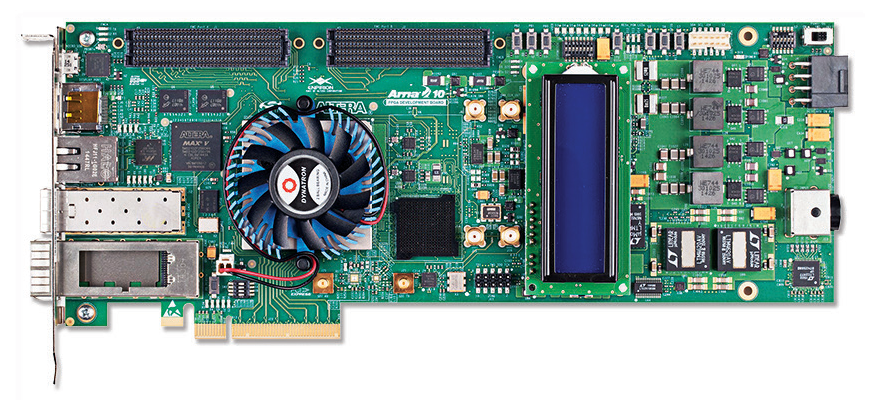
FPGA development kits allow system developers to evaluate an FPGA without having to design a complete system. Figures 1 and 2 show Altera’s new 20nm Arria 10 FPGAs and Arria 10 SoCs (System-on-Chip) development boards. These boards are tested and verified by Altera, exemplifying best design practices in layout, signal integrity and power management.

Figure 1. Arria 10 GX FPGA Development Kit Board

Figure 2. Arria 10 SoC Development Kit Board
Power Management for Core, System and I/O
The power management solution for high end FPGAs, including the Arria 10, should be carefully selected. A well thought-out power management design can reduce PCB size, weight and complexity, as well as lower power consumption and cooling costs. And it is essential to achieve optimal system performance. For example, the 0.95V at 105A supplied by the 12V DC/DC regulator powering the core of the Arria 10 GX FPGA in Figure 1 has several features that complement the power saving schemes of the SoC:
- The DC/DC regulator’s integrated 6-bit parallel VID interface is used by the Arria 10’s SmartVID to control the DC/DC regulator and reduce FPGA power consumption during static and dynamic states.
- The DC/DC regulator’s very low value DCR current sensing improves efficiency by minimizing power loss in the inductor. Temperature compensation maintains the accuracy or the DCR value at higher inductor temperature.
Table 1 summarizes the Arria 10 development kit’s power rails and functions shown in Figure 1. The table lists Linear Technology parts and descriptions for each function. Visit Altera, click on Arria and access technical details for the two boards presented here.
| Rail/Function | Part Number | Description |
| FPGA Core | LTC3877 + LTC3874 | 105A at 0.9V Regulator Seamlessly Interfaces with Arria 10 SmartVID |
| High Speed Transceivers | LTM4637 | 20A μModule® Regulator |
| Power UP/DOWN Sequencing, Voltage and Current Monitoring, Voltage Margining and Fault Management | LTC2977 | 8-Channel PMBus Power System Manager |
| PowerPath™ Management | LTC4357 | High Voltage Ideal Diode Controller |
| 3.3V Intermediate Bus from 12VIN | LTM4620 | Dual 13A or Single 26A μModule Regulator |
| Input Overvoltage Protection | LTC4365 | Overvoltage, Undervoltage and Reverse Supply Protection Controller |
| Housekeeping System Power and Power Management | LT1965, LT3082, LTC4352, LTC3025-1, LTC2418 | Low Noise Linear Regulators, 24-Bit ADC; Low Voltage Ideal Diode |
Customize the Power Tree with the LTpowerPlanner Design Tool
What if your power requirements differ from the designs exemplified in a development kit? For these cases, use the LTpowerPlanner® PC-based design tool to personalize and optimize a system’s power tree. Start with the suggestions given in the development kit; then easily reorganize power blocks, alter power ratings, compute efficiency and power loss, simulate each power block, select DC/DC regulator part numbers and authenticate a customized solution. LTpowerPlanner was used to generate the power trees (Figure 3) for the Arria 10 development kit’s FPGA and system requirements, and is available within the more encompassing LTpowerCAD® design tool, available for free download at LTpowerCad.

Figure 3. Power Tree for Arria 10 GX FPGA Board (Figure 1). Designed in LTpowerPlanner, An Analytical and Simple First Step Design Tool for Mapping System Power Requirements.
LTpowerCAD enables users to:
- Select specific Linear Technology DC/DC regulators to match a given power specification
- Select appropriate power components such as inductors, resistors and capacitors
- Optimize efficiency and power loss
- Optimize regulator loop stability, output impedance and load transient response
- Export the design to LTspice® for time domain simulation
Conclusion
Development kit design guides for Altera Arria 10 FPGAs and SoCs, as well as other Altera FPGAs including power trees and bill-of-materials are available at Altera. These development kits have been tested and verified by Altera or third-party developers.
