LTC3733
Info: : PRODUCTION
searchIcon
cartIcon

LTC3733

3-Phase, Buck Controllers for AMD CPUs

Show More showmore-icon

Info: : PRODUCTION tooltip
Part Models 4
1ku List Price Starting From $5.24
Features
  • 3-Phase Controller with Onboard MOSFET Drivers
  • Current Mode Control Ensures Current Sharing
  • Differential Amplifier Accurately Senses VOUT
  • ±5% Output Current Matching Optimizes Thermal Performance and Size of Inductors and MOSFETs
  • Reduced Input and Output Capacitance
  • Supports Active Voltage Positioning
  • VID Programmable Output Voltage from 0.8V to 1.55V (AMD Opteron CPU)
  • 6-Phase, 90A to 120A Operation
  • Output Power Good Indicator with Adaptive Blanking
  • 210kHz to 530kHz Per Phase, PLL, Fixed Frequency
  • Synchronizable (LTC3733-1)
  • PWM, Stage Shedding or Burst Mode® Operation
  • OPTI-LOOP® Compensation Minimizes COUT
  • Adjustable Soft-Start Current Ramping
  • Short-Circuit Shutdown Timer with Defeat Option
  • No_CPU Detection
  • 36-Lead Narrow SSOP and 38-Lead (5mm × 7mm) QFN
Additional Details
show more Icon

The LTC3733 family are PolyPhase® synchronous stepdown switching regulator controllers that drive all N-channel external power MOSFET stages in a phase-lockable, fixed frequency architecture. The 3-phase controller drives its output stages with 120° phase separation at frequencies of up to 530kHz per phase to minimize the RMS current dissipated by the ESR of both the input and output filter capacitors. The 3-phase technique effectively triples the fundamental frequency, improving transient response while operating each phase at an optimal frequency for efficiency and ease of thermal design. Light load efficiency is optimized by using a choice of output stage shedding or Burst Mode technology.

A differential amplifier provides true remote sensing of both the high and low sides of the output voltage at load points.

Soft-start and a defeatable, timed short-circuit shutdown protect the MOSFETs and the load. A foldback current circuit also provides protection for the external MOSFETs under short-circuit or overload conditions. An all-“1” VID detector turns off the regulator after 1µs timeout.

Applications

  • High Performance Notebook Computers
  • Servers, Desktop Computers and Workstations
Part Models 4
1ku List Price Starting From $5.24

close icon

Documentation

Part Model Pin/Package Drawing Documentation CAD Symbols, Footprints, and 3D Models
LTC3733CG#PBF
  • HTML
  • HTML
LTC3733CG#TRPBF
  • HTML
  • HTML
LTC3733CUHF-1#PBF
  • HTML
  • HTML
LTC3733CUHF-1#TRPBF
  • HTML
  • HTML

Filter by Model

reset

Reset Filters

Part Models

Product Lifecycle

PCN

Nov 18, 2019

- 19_0266

Laser Top Mark for SSOP36/44/48 Packages assembled in ADPG and UTAC

LTC3733CG#PBF

PRODUCTION

LTC3733CG#TRPBF

PRODUCTION

Filter by Model

reset

Reset Filters

Part Models

Product Lifecycle

PCN

Nov 18, 2019

- 19_0266

arrow down

Laser Top Mark for SSOP36/44/48 Packages assembled in ADPG and UTAC

LTC3733CG#PBF

PRODUCTION

LTC3733CG#TRPBF

PRODUCTION

Software & Part Ecosystem

Evaluation Kits 1

reference details image

DC648A

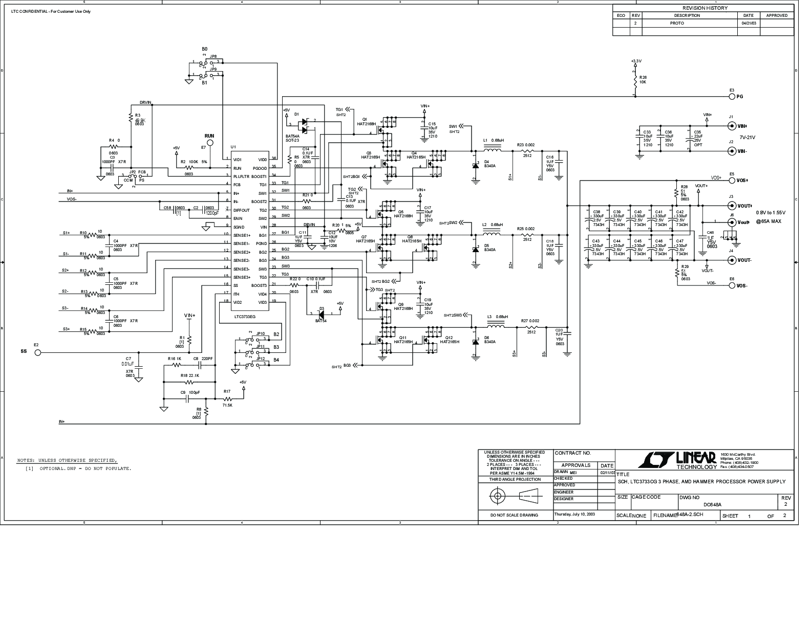
LTC3733CG Demo Board | 3-Phase, AMD Hammer Processor Power Supply, VIN = 7V to 21V, VOUT = 0.8V to 1.55V @ 65A

zoom

DC648A

LTC3733CG Demo Board | 3-Phase, AMD Hammer Processor Power Supply, VIN = 7V to 21V, VOUT = 0.8V to 1.55V @ 65A

LTC3733CG Demo Board | 3-Phase, AMD Hammer Processor Power Supply, VIN = 7V to 21V, VOUT = 0.8V to 1.55V @ 65A

Product Detail

Demonstration circuit 648 is a high current step-down PolyPhaseTM supply featuring the LTC3733 three-phase synchronous buck controller. It provides high performance power solutions for AMD OpteronTM and AthlonTM 64 processors. The switching frequency range of the LTC3733 is 210kHz to 530kHz. The input supply voltage range is 7V to 21V and the nominal VID programmable output voltage is 0.8V-1.55V. The demo board can supply 65A of output current.

Tools & Simulations 1

LTspice® is a powerful, fast and free simulation software, schematic capture and waveform viewer with enhancements and models for improving the simulation of analog circuits.

To launch ready-to-run LTspice demonstration circuits for this part:

Step 1: Download and install LTspice on your computer.

Step 2: Click on the link in the section below to download a demonstration circuit.

Step 3: If LTspice does not automatically open after clicking the link below, you can instead run the simulation by right clicking on the link and selecting “Save Target As.” After saving the file to your computer, start LTspice and open the demonstration circuit by selecting ‘Open’ from the ‘File’ menu.

Recently Viewed