LTC3626
Info : RECOMMENDED FOR NEW DESIGNS
searchIcon
cartIcon

LTC3626

20V, 2.5A Synchronous Monolithic Step-Down Regulator with Current and Temperature Monitoring

Show More showmore-icon

Info : RECOMMENDED FOR NEW DESIGNS tooltip
Part Models 4
1ku List Price Starting From $4.13
Features
  • 3.6V to 20V Input Voltage Range
  • Wide Output Voltage Range of 0.6V to 97% VIN Optimized for 0.6V to 6V
  • Low RDS(ON) Integrated Switches Provide Up to 95% Efficiency
  • Up to 2.5A of Output Current
  • Average Input and Output Current Monitoring
  • Programmable Average Input/Output Current Limit
  • Die Temperature Monitor and Programmable Limit
  • Adjustable Switching Frequency: 500kHz to 3MHz
  • External Frequency Synchronization
  • Current Mode Operation for Excellent Line and Load Transient Response
  • 0.6V Reference with 1% Accuracy Over Temperature
  • User Selectable Burst Mode® or Forced Continuous Operation
  • Short-Circuit Protected
  • Output Voltage Tracking Capability
  • Power Good Status Output
  • Available in Small, Thermally Enhanced, 20-Lead (3mm × 4mm) QFN Package
Additional Details
show more Icon

The LTC3626 is a high efficiency, monolithic synchronous buck regulator using a phase-lockable controlled on-time, current mode architecture capable of supplying up to 2.5A of output current. The operating supply voltage range is 3.6V to 20V, making it suitable for a wide range of power supply applications.

The operating frequency is programmable from 500kHz to 3MHz with an external resistor allowing the use of small surface mount inductors. For applications sensitive to switching noise, the LTC3626 can be externally synchronized over the same frequency range. An internal phase-locked loop aligns the on-time of the top power MOSFET to the internal or external clock. This unique controlled on-time architecture is ideal for high step-down ratio applications that demand high switching frequencies and fast transient response. An internal phase lock loop servos the on-time of the internal one-shot timer to match the frequency of the internal clock or an applied external clock.

The LTC3626 offers two operational modes: Burst Mode and forced continuous mode to allow the user to optimize output voltage ripple, noise and light load efficiency for a given application.

Applications

  • Distributed Power Systems
  • Battery-Powered Instruments
  • Point-of-Load Power Supply
Part Models 4
1ku List Price Starting From $4.13

close icon

Documentation

Part Model Pin/Package Drawing Documentation CAD Symbols, Footprints, and 3D Models
LTC3626EUDC#PBF
  • HTML
  • HTML
LTC3626EUDC#TRPBF
  • HTML
  • HTML
LTC3626IUDC#PBF
  • HTML
  • HTML
LTC3626IUDC#TRPBF
  • HTML
  • HTML

Software & Part Ecosystem

Evaluation Kits 1

reference details image

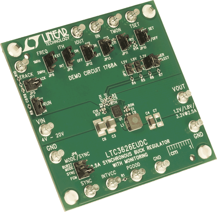
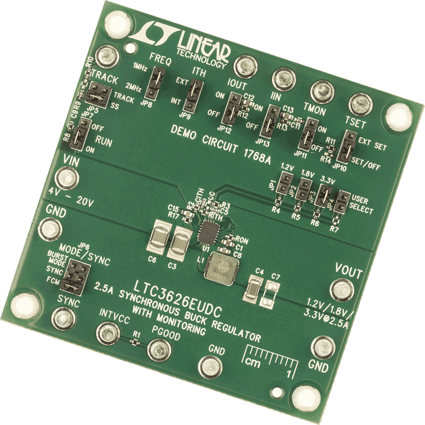
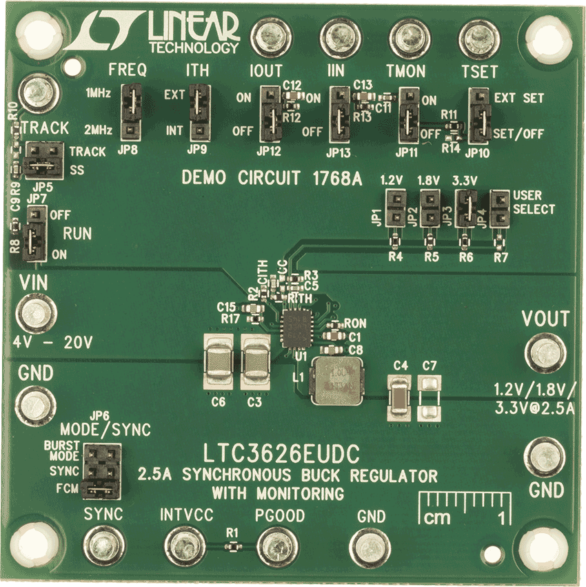
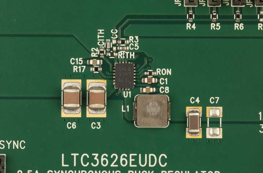
DC1768A

LTC3626EUDC Demo Board | 3.6V ≤ VIN ≤ 20V, VOUT = 0.6V @ 6V  2.5A, Current and Temp Monitoring

zoom

DC1768A

LTC3626EUDC Demo Board | 3.6V ≤ VIN ≤ 20V, VOUT = 0.6V @ 6V  2.5A, Current and Temp Monitoring

LTC3626EUDC Demo Board | 3.6V ≤ VIN ≤ 20V, VOUT = 0.6V @ 6V  2.5A, Current and Temp Monitoring

Product Detail

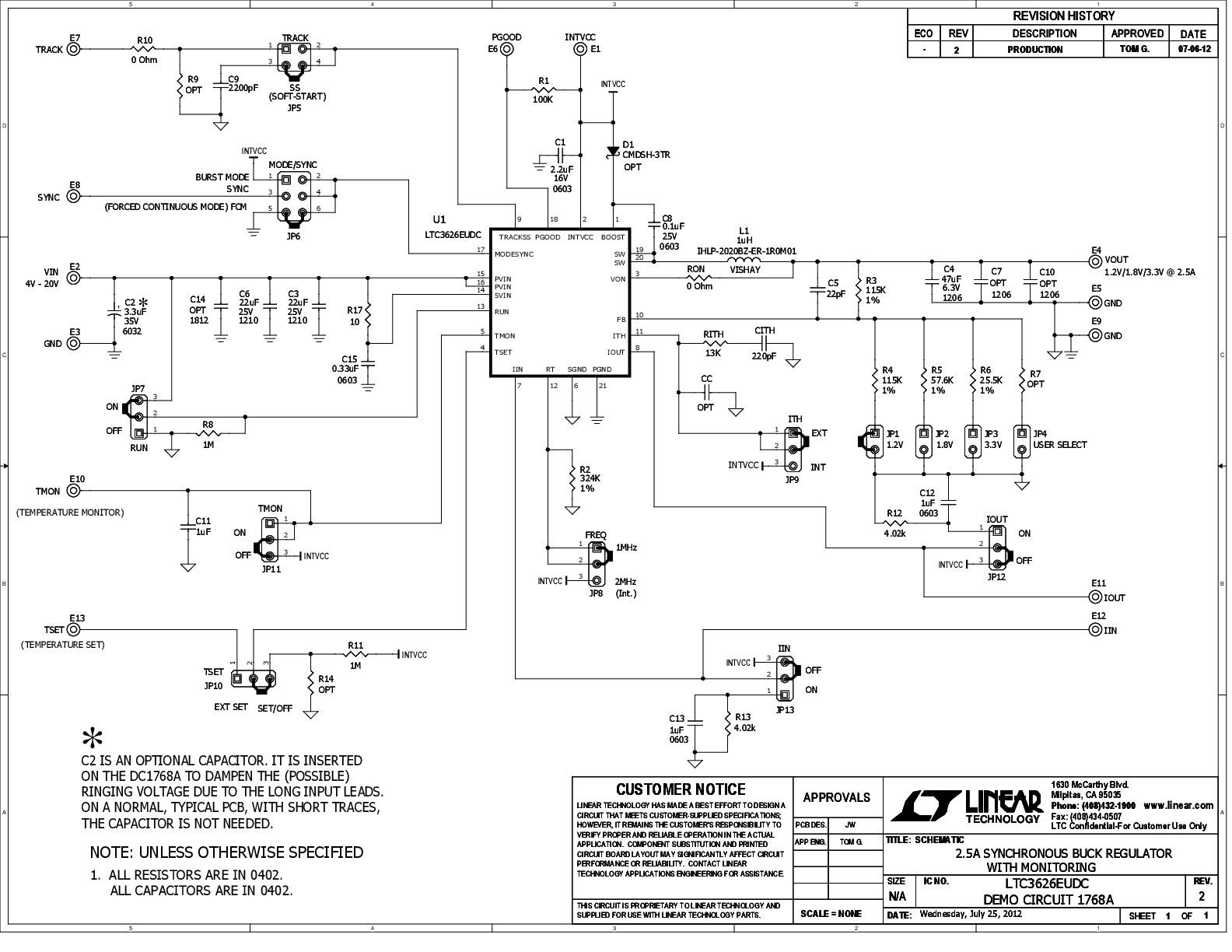
Demonstration circuit 1768A is a step-down converter, using the LTC3626 monolithic synchronous buck regulator, which has current and temperature monitoring capabilities. The 1768A has an input voltage range of 3.6V to 20V, and is capable of delivering up to 2.5A of output current. The output voltage range of the 1768A is 6V down to 0.6V.


Tools & Simulations 2

LTspice® is a powerful, fast and free simulation software, schematic capture and waveform viewer with enhancements and models for improving the simulation of analog circuits.

To launch ready-to-run LTspice demonstration circuits for this part:

Step 1: Download and install LTspice on your computer.

Step 2: Click on the link in the section below to download a demonstration circuit.

Step 3: If LTspice does not automatically open after clicking the link below, you can instead run the simulation by right clicking on the link and selecting “Save Target As.” After saving the file to your computer, start LTspice and open the demonstration circuit by selecting ‘Open’ from the ‘File’ menu.

Recently Viewed