ADPL12005

RECOMMENDED FOR NEW DESIGNS

20V, 5A/6A Fully Integrated Synchronous Buck Converters

Viewing:

Part Details

  • Multiple Functions for Small Size
    • Operating VIN Range of 3V to 20V
    • 20μA Quiescent Current in Skip Mode
    • Synchronous DC-DC Converter with Integrated Field-Effect Transistors (FETs)
    • 400kHz and 1.5MHz Fixed-Frequency Options
    • Internal Soft-Start
      • 2.5ms for 400kHz
      • 3.5ms for 1.5MHz
    • Programmable Output Voltage
      • 0.8V to 12V for 400kHz
      • 0.8V to 10V for 1.5MHz
    • 3.5mm x 3.75mm, 17-Pin FC2QFN
    • Symmetrical Package Offers Superior Electromagnetic Interference (EMI) Performance
  • Dual Phase Capability
    • Can be used in Dual-Phase Configuration for High-Power Design
    • Dynamic Current Sharing through Shared VEA Pin
    • Low-IQ Operation Capability in Dual Phase
  • Precise Output Voltage Monitoring with PGOOD
  • Forced–Pulse-WidthModulation (PWM) and Skip-Mode Operation
  • Low Dropout Operation
  • Overtemperature and Short-Circuit Protection
  • -40°C to +150°C Operating Junction Temperature Range
ADPL12005
20V, 5A/6A Fully Integrated Synchronous Buck Converters
ADPl12005-ADPL12006 Simplified Block Diagram ADPl12005-ADPL12006 Typical Application Circuit Single Phase Operation ADPl12005-ADPL12006 Pin Configuration ADPL12005 Chip Illustration
Add to myAnalog

Add product to the Products section of myAnalog (to receive notifications), to an existing project or to a new project.

Create New Project
Ask a Question

Documentation

Learn More
Add to myAnalog

Add media to the Resources section of myAnalog, to an existing project or to a new project.

Create New Project

Software Resources

Can't find the software or driver you need?

Request a Driver/Software

Tools & Simulations

EE-Sim Power® Tools 1

The EE-Sim DC-DC Converter Tool uses your requirements to quickly create a complete power design including a schematic, BOM with commercially available parts, and time and frequency domain simulations. Your customized schematic can be downloaded for further analysis in the standalone EE-Sim OASIS Simulator, featuring SIMPLIS and SIMetrix SPICE engines.

Start EE-Sim Now

Evaluation Kits

eval board
ADPL12006EVKIT

Evaluates: ADPL12005/ADPL12006

Features and Benefits

  • Input Supply Range from 3V to 20V
  • Adjustable Output Voltage Range between 0.8V and10V
  • Delivers up to 6A Output Current
  • Frequency Synchronization Input
  • Enable Input
  • Voltage-Monitoring PGOOD Output Available
  • Proven PCB Layout
  • Fully Assembled and Tested

Product Details

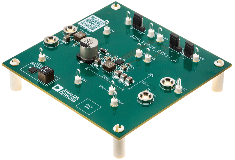
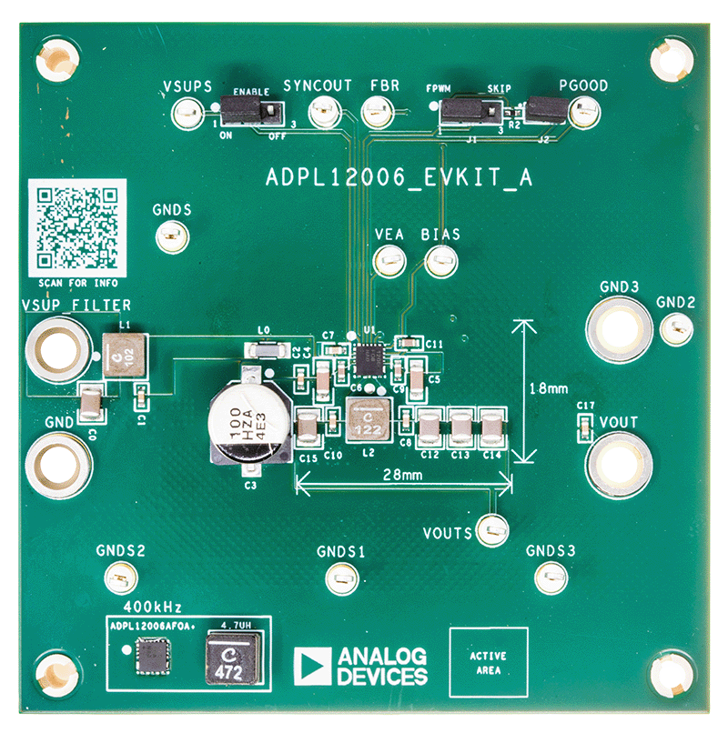
The ADPL12006 evaluation kit (EV kit) provides a proven design to evaluate the ADPL12005/ADPL12006, synchronous buck converter with 20μA quiescent current. The standard EV kit Printed circuit board (PCB), comes with an ADPL12006AFOB+ (1.5MHz, adjustable output) installed, and various test points and jumpers for evaluation. The EV kit output voltage is fixed and easily configured with minimum component changes. The default EV kit is designed to deliver up to 6A with an input voltage of 3V to 20V. Output voltage quality can be monitored by observing the PGOOD signal. The ADPL12006 EV kit can also be used to evaluate all variants of the ADPL12005 and ADPL12006.

ADPL12006EVKIT
Evaluates: ADPL12005/ADPL12006
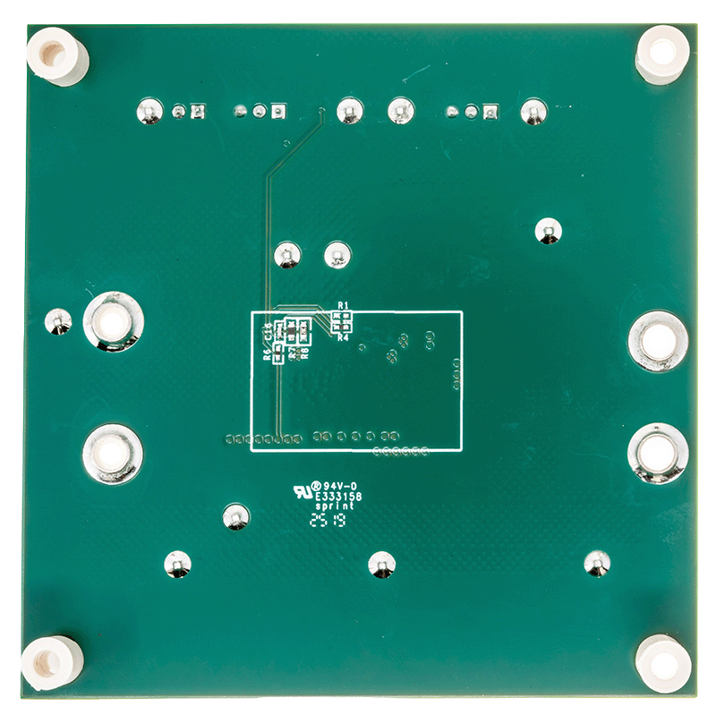
ADPL12006EVKIT Board Photo Angle View ADPL12006EVKIT Board Photo Top View ADPL12006EVKIT Board Photo Bottom View

Latest Discussions

No discussions on ADPL12005 yet. Have something to say?

Start a Discussion on EngineerZone®

Recently Viewed