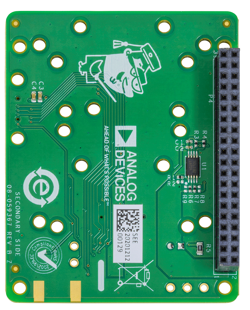
ADIS16490
NOT RECOMMENDED FOR NEW DESIGNSTactical Grade, Six Degrees of Freedom Inertial Sensor
- Part Models
- 1
- 1ku List Price
- Starting From $3427.18
Overview
- Triaxial, digital gyroscope, ±100°/sec dynamic range
- ±0.05° axis to axis misalignment error
- ±0.25° axis to package misalignment error
- 1.8°/hr in run bias stability
- 0.09°/√hr angular random walk
- Triaxial, digital accelerometer, ±8 g
- 3.6 μg in run bias stability
- Triaxial, delta angle and delta velocity outputs
- Factory calibrated sensitivity, bias, and axial alignment
- Calibration temperature range: −40°C to +85°C
- Serial peripheral interface (SPI) compatible
- Programmable operation and control
- Automatic and manual bias correction controls
- 4 finite impulse response (FIR) filter banks, 120 configurable taps
- Digital input/output (I/O): data ready, external clock
- Sample clock options: internal, external, or scaled
- On demand self test of inertial sensors
- Single-supply operation: 3.0 V to 3.6 V
- 2000 g shock survivability
- Operating temperature range: −40°C to +105°C
The ADIS16490 is a complete inertial system that includes a triaxis gyroscope and a triaxis accelerometer. Each inertial sensor in the ADIS16490 combines industry leading iMEMS® technology with signal conditioning that optimizes dynamic performance. The factory calibration characterizes each sensor for sensitivity, bias, alignment, and linear acceleration (gyroscope bias). As a result, each sensor has its own dynamic compensation formulas that provide accurate sensor measurements.
The ADIS16490 provides a simple, cost effective method for integrating accurate, multiaxis inertial sensing into industrial systems, especially when compared with the complexity and investment associated with discrete designs. All necessary motion testing and calibration are part of the production process at the factory, greatly reducing system integration time. Tight orthogonal alignment simplifies inertial frame alignment in navigation systems. The SPI and register structure provide a simple interface for data collection and configuration control.
The ADIS16490 uses the same footprint and connector system as the ADIS16375, ADIS16480, ADIS16485, and ADIS16488A, which greatly simplifies the upgrade process. The ADIS16490 is packaged in a module that is approximately 47 mm × 44 mm × 14 mm and includes a standard connector interface.
Applications
- Precision instrumentation, stabilization
- Guidance, navigation, control
- Avionics, unmanned vehicles
- Precision autonomous machines, robotics
Documentation
Data Sheet 1
Technical Articles 1
Product Highlight 1
Device Drivers 1
Product Highlight 1
Webcast 3
ADI has always placed the highest emphasis on delivering products that meet the maximum levels of quality and reliability. We achieve this by incorporating quality and reliability checks in every scope of product and process design, and in the manufacturing process as well. "Zero defects" for shipped products is always our goal. View our quality and reliability program and certifications for more information.
| Part Model | Pin/Package Drawing | Documentation | CAD Symbols, Footprints, and 3D Models |
|---|---|---|---|
| ADIS16490BMLZ | 24-Lead Module with Connector Interface |
| Part Models | Product Lifecycle | PCN |
|---|---|---|
|
Sep 21, 2020 - 19_0152 ADIS1649X IMU Package Dimension Tolerance Change |
||
| ADIS16490BMLZ | ||
|
Apr 1, 2020 - 20_0175 Addition of Analog Devices, Inc. General Trias (ADGT) as Qualified Test Site for iSensor inertial measurement unit (IMU) products |
||
| ADIS16490BMLZ | ||
|
Mar 30, 2020 - 19_0080 ADIS1649X Layout Change |
||
| ADIS16490BMLZ | ||
|
Jun 21, 2017 - 17_0122 ADIS16490 Modification to Add Brown-Out Protection |
||
| ADIS16490BMLZ | ||
This is the most up-to-date revision of the Data Sheet.
Software Resources
Evaluation Software 0
Can't find the software or driver you need?


