AD5143

PRODUCTION

Quad Channel, 128-/256-Position, I2C, Nonvolatile Digital Potentiometer

Viewing:

Overview

  • 10 kΩ and 100 kΩ resistance options
  • Resistor tolerance: 8% maximum
  • Wiper current: ±6 mA
  • Low temperature coefficient: 35 ppm/°C
  • Wide bandwidth: 3 MHz
  • Fast start-up time < 75 μs
  • Linear gain setting mode
  • Single- and dual-supply operation
  • Wide operating temperature: −40°C to +125°C
  • 3 mm × 3 mm package
AD5143
Quad Channel, 128-/256-Position, I2C, Nonvolatile Digital Potentiometer
AD5123/AD5143 Functional Block Diagram AD5123/AD5143 Pin Configuration
Add to myAnalog

Add product to the Products section of myAnalog (to receive notifications), to an existing project or to a new project.

Create New Project
Ask a Question

Documentation

Learn More
Add to myAnalog

Add media to the Resources section of myAnalog, to an existing project or to a new project.

Create New Project

Tools & Simulations


Evaluation Kits

EVAL-AD5143

AD5143 Evaluation Board

Features and Benefits

  • Full featured evaluation board in conjunction with low voltage digiPOT motherboard (EVAL-MB-LV-SDZ)
  • Various test circuits
  • Various ac/dc input signals
  • PC control via a separately purchased system demonstration platform (SDP-B or SDP-S)
  • PC software for control

Product Details

With versatile programmability, the AD5143 allows multiple modes of operation, including read/write access in the RDAC and EEMEM registers, increment / decrement of resistance, resistance changes in ±6 dB scales, wiper setting read-back, and extra EEMEM for storing user-defined information, such as memory data for other components or a lookup table.

The AD5143 supports a dual-supply ±2.25 V to ±2.75 V operation and a single-supply 2.3 V to 5.5 V operation, making the device suitable for battery-powered applications and many other applications. In addition, the AD5143 can be configured as a versatile I2C or SPI serial interface. The EVAL-AD5143DBZ can operate in single-supply or dual-supply mode and incorporates an internal power supply from the USB.

Complete specifications for the AD5143 part can be found in the AD5143 data sheet.

eval board
EVAL-AD5143-2DBZ

Evaluating the AD5143 Digital Potentiometer

Features and Benefits

  • Full featured evaluation board for the AD5143 in conjunction with low voltage digital potentiometer (digiPOT) motherboard (EVAL-MB-LV-ARDZ)
  • Various test circuits
  • Various power solutions
  • Various AC/DC input signals
  • PC control in conjunction with the Analog Devices, Inc., EVALSDP-CK1Z (SDP-K1) controller board

Product Details

This user guide describes the evaluation board for evaluating the AD5143—a digital potentiometer with 256 positions and nonvolative memory. With versatile programmability, the AD5143 allows multiple modes of operation, including read/write access in the RDAC and EEPROM registers, increment/decrement of resistance, resistance changes in ±6 dB scales, wiper setting readback, and extra electronically erasable programmable read‐only memory (EEPROM) for storing user-defined information, such as memory data for other components or a lookup table.

The AD5143 supports a dual supply (±2.25V to ±2.75V) operation and a single supply (+2.3V to +5.5V) operation, making the device suitable for battery-powered applications and many other applications. The EVAL-MB-LV-ARDZ incorporates an internal power supply from the USB and provides on-board +5V, +3V, +2.5V/−2.5V supplies to the EVAL-AD5143-2DBZ.

The EVAL-MB-LV-ARDZ interfaces with the USB port of a PC via the system demonstration platform (SDP-K1) controller board. The ACE software is available for download on the EVAL-AD5143-2DBZ product page. This software enables the user to program the AD5143. A peripheral module interface (PMOD) connection is also available that allows the connection of different microcontrollers to the EVAL-MB-LV-ARDZ without the SDP-K1 controller board. Note that when a microcontroller is used through the PMOD connection, the SDP-K1 board must be disconnected, and the user cannot use the ACE software.

Complete specifications for the AD5143 part can be found in the AD5143 data sheet, which is available from Analog Devices, and must be consulted in conjunction with this user guide when using the evaluation board.

eval board
EVAL-AD5143-2DBZ

Evaluating the AD5143 Digital Potentiometer

Features and Benefits

  • Full featured evaluation board for the AD5143 in conjunction with low voltage digital potentiometer (digiPOT) motherboard (EVAL-MB-LV-ARDZ)
  • Various test circuits
  • Various power solutions
  • Various AC/DC input signals
  • PC control in conjunction with the Analog Devices, Inc., EVALSDP-CK1Z (SDP-K1) controller board

Product Details

This user guide describes the evaluation board for evaluating the AD5143—a digital potentiometer with 256 positions and nonvolative memory. With versatile programmability, the AD5143 allows multiple modes of operation, including read/write access in the RDAC and EEPROM registers, increment/decrement of resistance, resistance changes in ±6 dB scales, wiper setting readback, and extra electronically erasable programmable read‐only memory (EEPROM) for storing user-defined information, such as memory data for other components or a lookup table.

The AD5143 supports a dual supply (±2.25V to ±2.75V) operation and a single supply (+2.3V to +5.5V) operation, making the device suitable for battery-powered applications and many other applications. The EVAL-MB-LV-ARDZ incorporates an internal power supply from the USB and provides on-board +5V, +3V, +2.5V/−2.5V supplies to the EVAL-AD5143-2DBZ.

The EVAL-MB-LV-ARDZ interfaces with the USB port of a PC via the system demonstration platform (SDP-K1) controller board. The ACE software is available for download on the EVAL-AD5143-2DBZ product page. This software enables the user to program the AD5143. A peripheral module interface (PMOD) connection is also available that allows the connection of different microcontrollers to the EVAL-MB-LV-ARDZ without the SDP-K1 controller board. Note that when a microcontroller is used through the PMOD connection, the SDP-K1 board must be disconnected, and the user cannot use the ACE software.

Complete specifications for the AD5143 part can be found in the AD5143 data sheet, which is available from Analog Devices, and must be consulted in conjunction with this user guide when using the evaluation board.

EVAL-AD5143
AD5143 Evaluation Board
EVAL-AD5143-2DBZ
Evaluating the AD5143 Digital Potentiometer
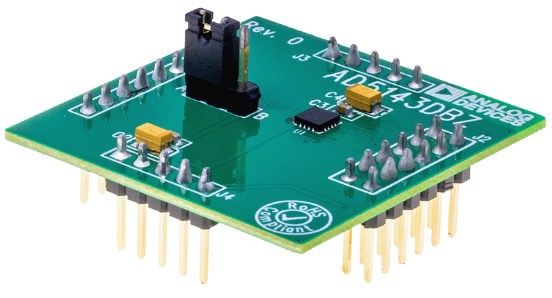
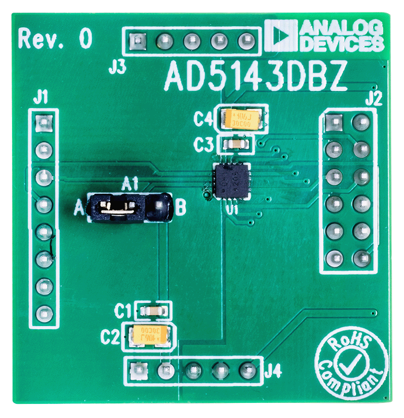
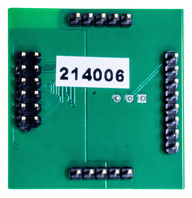
EVAL-AD5143-2DBZ Evaluation Board Angle View EVAL-AD5143-2DBZ Evaluation Board Top View EVAL-AD5143-2DBZ Evaluation Board Bottom View
EVAL-AD5143-2DBZ
Evaluating the AD5143 Digital Potentiometer
EVAL-AD5143-2DBZ Evaluation Board Angle View EVAL-AD5143-2DBZ Evaluation Board Top View EVAL-AD5143-2DBZ Evaluation Board Bottom View

Latest Discussions

Recently Viewed