MAX32690
RECOMMENDED FOR NEW DESIGNSArm Cortex-M4 with FPU Microcontroller and Bluetooth LE 5 for Industrial and Wearables
- Part Models
- 12
- 1ku List Price
- Starting From $19.49
Overview
- Ultra-Efficient Microcontroller for Battery-Powered Applications
- 120MHz Arm Cortex-M4 Processor with FPU
- Ultra-Low-Power, 32-Bit RISC-V (RV32) Coprocessor Available to Offload Data Processing
- Multiple Internal Low-Power Oscillators
- 32.768kHz RTC Clock (Requires External Crystal)
- 3.25MB Internal Flash, 1MB Internal SRAM
- 85μW/MHz ACTIVE Mode at 1.1V
- 1.8V and 3.3V I/O with No Level Translators
- External Flash and SRAM Expansion Interfaces
- Bluetooth 5.2 LE Radio
- Fully Open-Source Bluetooth 5.2 Stack Available
- High-Throughput (2Mbps) Mode
- Long-Range (125kbps and 500kbps) Modes
- Rx Sensitivity: -97dBm; Tx Power: +4.5dBm
- Single-Ended Antenna Connection (50Ω)
- 32MHz External Crystal Required
- Optimal Peripheral Mix Provides Platform Scalability
- 16-Channel DMA
- Up to Five Quad-SPI Controllers/Targets
- Up to Four UARTs with Flow Control
- Up to Three I2C Interfaces
- I2S Interface
- Up to Eight External Channel, 12-Bit 1Msps SAR ADCs with Temperature Sensor Channel
- USB 2.0 Hi-Speed Device
- Up to 16 Pulse Train Engines
- Up to Four 32-Bit/Dual 16-Bit Timers with 8mA High Drive
- Up to Two 32-Bit/Dual 16-Bit Low-Power Timers
- Two CAN 2.0B Controllers
- Up to Four Micropower Comparators
- 1-Wire Controller
- Cryptographic Tool Box (CTB) for IP/Data Security
- AES-128/192/256, SHA-2 Engine, MAA, TRNG
- Extensive Security Features
- Arm Memory Protection Unit (MPU)
- Memory Decryption Integrity Unit (MDIU) for External SPI Memory
- Physically Unclonable Function (PUF)
- 128-Bit Unique Serial Number (USN)
- Optional Secure Communications Protocol Bootloader (SCPBL)
The MAX32690 microcontroller (MCU) is an advanced system-on-chip (SoC) featuring an Arm® Cortex®-M4F CPU, large flash and SRAM memories, and Bluetooth® 5.2 Low Energy (LE) radio. This device unites processing horsepower with the connectivity required for IoT applications.
The MAX32690 is qualified to operate over the -40°C to +105°C range, which is ideal for industrial environments. This device is available in 68-pin TQFN-EP (0.40mm pitch), 140-bump WLP (0.35mm pitch), and 144-CTBGA (0.8mm pitch) packages.
The integrated Bluetooth 5.2 Low Energy (LE) radio supports long-range (coded) and high-throughput modes. A RISC-V core optionally handles timing-critical controller tasks, freeing the programmer from Bluetooth LE interrupt latency concerns.
Internal code and SRAM space can be expanded offchip through two quad-SPI execute-in-place (SPIXF and SPIXR) interfaces up to 512MB each.
A cryptographic toolbox (CTB) provides a modular arithmetic accelerator (MAA), advanced encryption standard (AES) engine, TRNG, and SHA-2 engine. The device also provides extensive security features including a 128-bit unique serial number (USN), physically unclonable function (PUF), secure nonvolatile key storage, a memory decryption integrity unit (MDIU) for SPIXF and SPIXR, and the Arm memory protection unit (MPU). The optional secure communications protocol boot loader (SCPBL) provides an immutable root of trust, secure boot with flash integrity validation using ECDSA, and secure firmware update ability.
Many high-speed interfaces are supported on the device, including multiple QSPI, UART, CAN 2.0B, and I2C serial interfaces, plus one I2S port for connecting to an audio codec. Most interfaces support DMA-driven transfers between memory (flash or SRAM) and a peripheral. A 12-input (8 external), 12-bit SAR ADC samples analog data at up to 1Msps.
Applications
- Fitness/Health Wearables
- Portable and Wearable Wireless Medical Devices
- Asset Tracking
- Industrial Sensors and Networks
Documentation
Data Sheet 1
User Guide 2
Device Drivers 1
Analog Dialogue 3
Webcast 1
ADI has always placed the highest emphasis on delivering products that meet the maximum levels of quality and reliability. We achieve this by incorporating quality and reliability checks in every scope of product and process design, and in the manufacturing process as well. "Zero defects" for shipped products is always our goal. View our quality and reliability program and certifications for more information.
| Part Model | Pin/Package Drawing | Documentation | CAD Symbols, Footprints, and 3D Models |
|---|---|---|---|
| MAX32690EXE+ | Chip Array Thin Core Ball Grid Array | ||
| MAX32690EXE+T | Chip Array Thin Core Ball Grid Array | ||
| MAX32690EXEBL+ | Chip Array Thin Core Ball Grid Array | ||
| MAX32690EXEBL+T | Chip Array Thin Core Ball Grid Array | ||
| MAX32690GTK+ | LFCSP | ||
| MAX32690GTK+T | LFCSP | ||
| MAX32690GTKBL+ | LFCSP | ||
| MAX32690GTKBL+T | LFCSP | ||
| MAX32690GWE+ | WLCSP | ||
| MAX32690GWE+T | WLCSP | ||
| MAX32690GWEBL+ | WLCSP | ||
| MAX32690GWEBL+T | WLCSP |
| Part Models | Product Lifecycle | PCN |
|---|---|---|
|
Nov 20, 2025 - 2535 PIN/ERRATA |
||
| MAX32690EXE+ | PRODUCTION | |
| MAX32690EXE+T | PRODUCTION | |
| MAX32690EXEBL+ | PRODUCTION | |
| MAX32690EXEBL+T | PRODUCTION | |
| MAX32690GTK+ | PRODUCTION | |
| MAX32690GWE+ | PRODUCTION | |
| MAX32690GWE+T | PRODUCTION | |
|
Aug 20, 2025 - 2508 DESIGN |
||
| MAX32690EXE+ | PRODUCTION | |
| MAX32690GTK+ | PRODUCTION | |
| MAX32690GWE+ | PRODUCTION | |
| MAX32690GWE+T | PRODUCTION | |
This is the most up-to-date revision of the Data Sheet.
Software Resources
Device Drivers 1
EdgeBench NEW
EdgeBench is a secure, cloud‑based platform for remotely benchmarking and evaluating AI/ML models on Analog Devices’ edge hardware.
View DetailsCodeFusion Studio™
The multi award winning CodeFusion Studio (CFS) is an embedded software development platform accelerating the development of AI-enabled embedded systems.
View DetailsEvaluation Software 1
MAX32xxx-MAX78xxx MSDK Software
Can't find the software or driver you need?
Tools & Simulations
Evaluation Kits


Arduino Form-factor Development Platform Based on MAX32690 ARM Cortex-M4 Microcontroller
Resources
Software


MAX32690 Evaluation Kit
Resources
Software


Scalable BMS Kit for Cell and Pack Monitoring
Resources
Software


ADIN6310 Field Switch Reference Design User Guide
Resources


Complete Ethernet-APL Field Device Platform
Resources
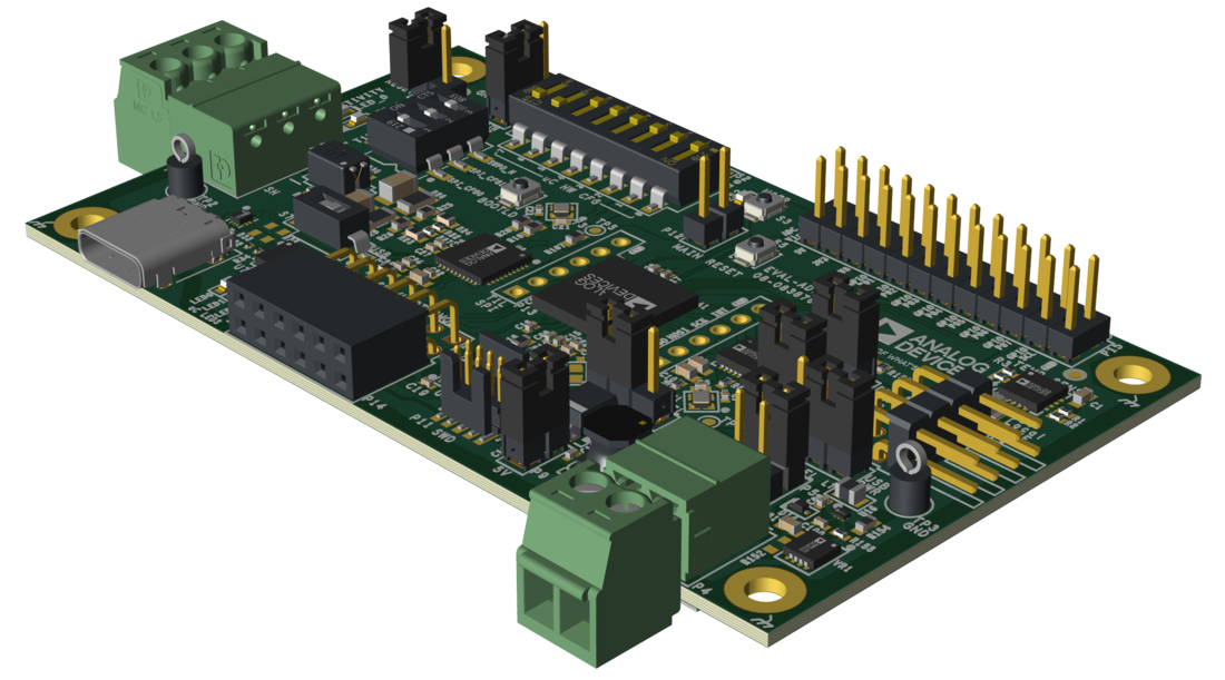
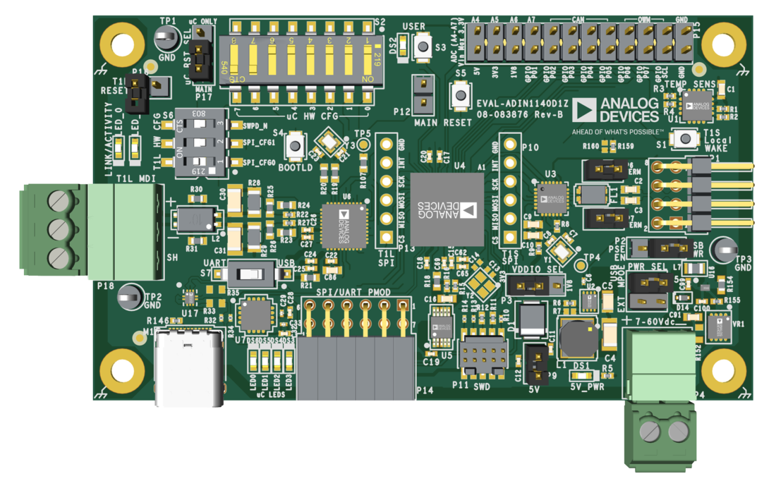
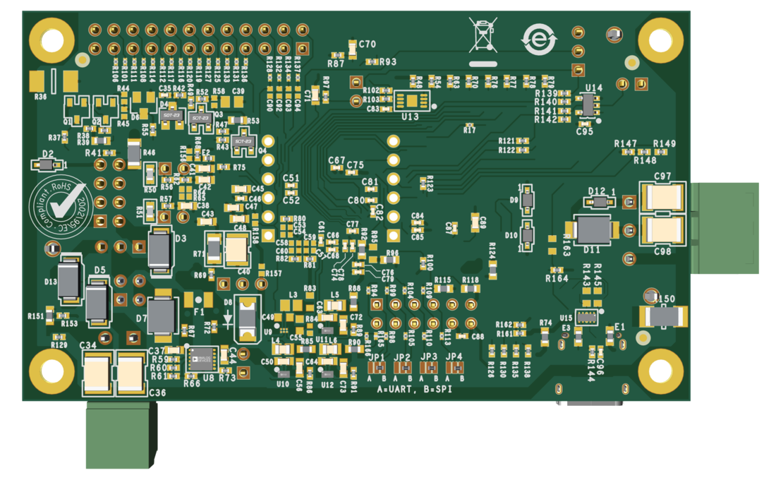
Evaluating the ADIN1140 10BASE-T1S Industrial Multidrop Evaluation Platform Board