ADRV9032R

RECOMMENDED FOR NEW DESIGNS

Integrated 2T2R TDD and FDD RadioVerse Transceiver with Dual Observation Paths

Viewing:

Overview

  • 2 differential transmitters
  • 2 differential receivers
  • 2 differential observation receivers
  • LO tunable range: 450 MHz to 7125 MHz
  • RF range: 350 MHz to 7225 MHz1
  • Maximum transmitter large-signal bandwidth: 200 MHz
  • Maximum transmitter synthesis bandwidth: 450 MHz
  • Maximum receiver signal bandwidth: 200 MHz
  • Maximum observation receiver signal bandwidth: 450 MHz
  • Fully integrated fractional-N RF synthesizer
  • Fully integrated clock synthesizer
  • Dual external LO inputs supporting operation up to 6 GHz
  • JESD204B and JESD204C digital interface: up to 16.5 Gbps
  • TDD and FDD operation
  • Simplifying thermal and power consumption challenges
    • 4.82 W power consumption for the TDD mode, enabled use case with 200 MHz iBW/OBW2

The ADRV9032R is a highly integrated, RF agile transceiver offering two transmitters, two observation receivers for monitoring transmitter channels, two receivers, integrated local oscillator (LO) and clock synthesizers, and digital-signal processing functions to provide a complete transceiver solution. The device provides the high radio performance and low-power consumption demanded by cellular infrastructure applications, software-defined radios, portable instruments, and military communications.

The receiver and transmitter signal paths use a zero-IF (ZIF) architecture that provides wide bandwidth with dynamic range suitable for non-contiguous multicarrier applications. The ZIF architecture has the benefits of low power and RF and bandwidth agility. The lack of aliases and out-of-band images eliminates anti-aliasing and image filters, reducing system size and cost, and making band independent solutions possible.

Please see the Data Sheet for the full description.

APPLICATIONS

  • Software defined radios
  • Portable instrumentation
  • Military communications
  • General-purpose radios
  • Wireless infrastructure
  • TDD and FDD applications

ADRV9032R
Integrated 2T2R TDD and FDD RadioVerse Transceiver with Dual Observation Paths
ADRV9032R Functional Block Diagram ADRV9032R Chip Illustration
Add to myAnalog

Add product to the Products section of myAnalog (to receive notifications), to an existing project or to a new project.

Create New Project
Ask a Question

Documentation

Learn More
Add to myAnalog

Add media to the Resources section of myAnalog, to an existing project or to a new project.

Create New Project

Software Resources

Can't find the software or driver you need?

Request a Driver/Software

Evaluation Kits

eval board
EVAL-ADRV903x

ADRV903x Evaluation System User Guide

Product Details

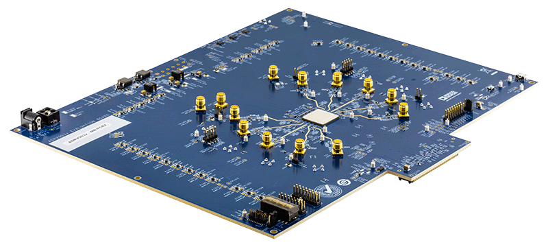
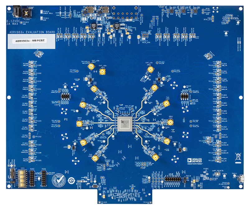
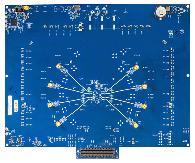
The ADRV903x family evaluation system enables customers to evaluate an ADRV903x device without having to develop custom hardware or software. The system is comprised of an ADRV903x customer evaluation (CE) board and an ADS10-V1EBZ motherboard with accompanying wall adapter power supplies for both. The evaluation software uses the Analysis | Control | Evaluation (ACE) software developed by Analog Devices, Inc., extended by an ADRV903x specific board plugin. This plugin can be run with ACE on a Windows® host PC communicating with the ADS10-V1EBZ motherboard using Ethernet. The ADS10-V1EBZ functions as a baseband processor running an application (ADRV903x command server) for controlling and communicating with the ADRV903x device.

This document also serves as a quick startup guide for the ADRV903x Configurator, which is built into the ADRV903x board plugin for ACE. The ADRV903x Configurator allows the user to explore various configurations of an ADRV903x device to arrive at a desired use case configuration. The ADRV903x Configurator also provides an overview of the frequency responses of the receiver (Rx), transmitter (Tx), and the observation receiver (ORx) datapaths for a chosen configuration.

This user guide details the steps required to install the ADRV903x evaluation software, program an existing use case, and evaluate the ADRV903x transmitter, receiver, and observation receiver datapaths. The ADRV903x Configurator sections of this user guide enable the user to generate a new use case and view its corresponding datapath configurations and filter graphs for the ADRV903x. Note that this document updates as the ADRV903x Configurator development progresses and as additional functions are added to the tool.

EVAL-ADRV903x
ADRV903x Evaluation System User Guide
EVAL-ADRV903x Board Photo Angle View EVAL-ADRV903x Board Photo Top View EVAL-ADRV903x Board Photo Bottom View

Latest Discussions

No discussions on ADRV9032R yet. Have something to say?

Start a Discussion on EngineerZone®

Recently Viewed