Self-Starting Can Be Hard to Do - Understanding Power-on-Reset Requirements in Regulators and Bandgaps
摘要
Self-starting is a necessary but sometimes difficult task, whether it is motivating humans, starting cold automobiles, or providing power-on-reset (POR) for ICs. PORs ensure systems start in known and safe states. We will discuss several misapplications of this technology and how designers can avoid startup problems.
A similar version of this article appeared in the November 30, 2011 issue of How2Power Today magazine.
Introduction
Self-starting or self-motivation is a good quality to look for when hiring sales and field application engineers. Another kind of a self-starter was invented by Charles Kettering for automobiles. Originally, automobiles required a hand crank to start the gasoline (petrol) engine. If the engine "backfired," it could run backward for a moment, breaking bones in a person's hand, wrist, and arm.
Similarly, many integrated circuits (IC) require special handling at power-up. Analog and digital circuits may need to be placed in predictable conditions at startup. To do that, we use circuits that are commonly called power-on-reset (POR) circuits.
POR makes sure that there is an orderly and predictable sequence of events during power-up. For example, circuits that supply bias currents in the circuit need to be available and stable to assure proper control of the circuit. One case that consumers notice this is in a stereo system. The audio can be delayed by 10 seconds or so after the power is applied, to protect the amplifier and speakers from big pops (transients). An amplifier feeding a speaker typically is biased at half the power-supply level. That silence out of the speaker is a quiescent DC voltage. While the quiescent bias level is being established during power-up, there can be sudden jumps that would cause ugly pops and destroy the speakers. That is why savvy audiophiles would never risk damage by plugging and unplugging equipment with power on.
Why Power-Supply Sequencing as a Part of POR?
Power-supply sequencing is a subject that takes volumes to explain. Years ago when three-terminal linear voltage regulators came on the market, a defect was discovered in systems with both positive and negative power rails. If the opposite voltage rail came up first, the regulator output would be pulled toward that opposite rail. At best, the regulator would not start, at worst it would burn up in a glorious plume of smoke.
Application notes flourished as manufacturers recommended adding diodes to prevent this occurrence. Soon the manufacturers added this requirement to the design definition, and the issue ceased to exist. That is, except where it was difficult or impossible to solve—some negative voltage regulators still needed diodes.
The Startup Surprise Party
With a Positive Voltage Regulator
A few years ago, a precision positive-voltage regulator was found to not start under all conditions if the output is pulled below ground. In this regulator family, there were parts available in three temperature ranges: 0 to +70°C, -40°C to +85°C, and -55°C to +125°C. Some engineers decided to use the 0 to +70°C range for cost reasons. In their application, they understood that the part could exceed 100°C under unusual circumstances. Since this was unlikely when the part was not operating, they proceeded.
Being diligent engineers, they checked their concept by testing 100 parts while heating them to 135°C. They all passed. After the product was in the field, they saw a small number of soft failures, in which a unit would fail but then recover.
With a "problem" unit in the lab, engineers looked carefully to find that the output of the voltage reference was being pulled below ground in the off state. They discovered that 2% to 3% of the references would fail to start, if they were heated above 105°C and had a negative voltage on the output. This was obviously an off-data-sheet use, both for negative voltage and temperature. When the designer contacted the manufacturer for advice, manufacturers were surprised that the parts did not start only when they were hot.
With a Voltage Reference
A voltage reference is a precision, low-current, low-temperature-coefficient voltage regulator. In Figure 1, the voltage reference op amp's negative input (feedback node) is connected to the output pin. The top of the resistor over the buried zener or bandgap can be connected to the input power, an internal power regulator, or to the output. A resistor can also be represented as a current source. Now, imagine that the positive supply is off and a negative voltage is applied to the output node. As power is applied, the circuit may not be able to establish proper bias voltages in the op amp, and some internal parasitic capacitances may stay charged, thus keeping the circuit off.
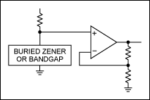
Figure 1. A simplified diagram of a typical voltage reference.
With an Op Amp
The op amp input structure in Figure 2 shows a lower-current source. Some components inside the IC are isolated from both ground and each other with back-biased diodes. Some parts have parasitic (unused) diodes and transistors that are part of their structure. The parasitic components are biased off in normal use and have no effect on the operation. If that current source is pulled negative, a parasitic component can become forward-biased, clamping the device in a nonoperating condition. Sometimes the parasitic device acts like a triac, staying on until the power is removed. In a worst-case scenario, this can destroy the device.
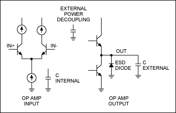
Figure 2. Inside the op amp.
With Capacitors
Inside the IC, there are capacitors added for frequency compensation, as well as unwanted stray capacitance. Those nodes, if charged below ground, may not have a current source available to give them a positive charge and allow the circuit to function.
The output circuit must be biased to turn on the top transistor to charge the external capacitance. Because the negative op-amp feedback node is connected to the output, the output must rise into linear operation for the circuit to function. Most ICs have electrostatic discharge (ESD) protection. This usually consists of diodes and zener diodes, as shown in Figure 3.
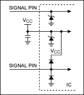
Figure 3. Typical ESD structures protect the rest of the integrated circuit.
With ESD Problems
ESD protection is necessary, since high voltages can destroy an IC. If the voltage goes above the absolute maximum rating of the IC-fabrication process, the active components will go into a zener mode. They will then eventually break down, as currents increase and the elements go into avalanche mode, drawing huge currents and fusing the silicon. Voltage in the negative direction that is greater than the absolute maximum will also draw excessive current and destroy the IC.
With Bandgap References
Bandgap references, as shown in Figure 4, also have startup issues. A bandgap consists of two forward-biased semiconductors with different currents. An inversion in one path causes the two currents to balance at a design point. One path produces a voltage with a negative temperature coefficient (tempco), the other a positive tempco.
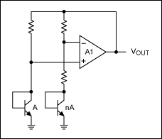
Figure 4. A common bandgap configuration.
The operating point is chosen so that the difference will create a signal that is proportional to absolute temperature (PTAT). A perfect design would have no voltage change with temperature. Unfortunately, the op amp will balance and be stable at two points: the design current and at zero current. However, at zero current, there is nothing that tells the circuit which way to servo or correct.
A Bandgap Reference Calculator aids in the design and analysis of a Brokaw bandgap reference circuit. It calculates all circuit parameters and the output voltage as a function of junction temperature. The first-order effects of trimming and second-order curvature correction are simulated. This free calculator is available at Design Tools & Calculators. It will run on an HP® 50g calculator or on a PC with a free emulator.
Solving the POR Problems
The voltage reference of Figure 1 works because there is a separate startup circuit that unbalances the currents in the two bandgap paths when there is zero current. The fact that it operates at room temperature and fails at hotter temperatures proves that the startup circuit is "weak" when hot, where there are higher leakage currents. The designer must, therefore, create a middle ground between building a startup circuit that is too weak (that can fail to start) and is too strong (that it affects normal operation). Making a bandgap start is a difficult issue and there are dozens of patents on the subject.
The fix in this case may be very simple. Assuming that the circuit leaking the negative voltage cannot be fixed, we will clamp the reference's output. The existing ESD diodes inside the IC are silicon (Figure 3), so they naturally clamp the negative voltage at 0.6V to 0.7V (or there could be two diodes in series that clamp at 1.2V). Add a small Schottky diode to the reference output. In normal operation, the diode will be back-biased and out of the circuit. The reverse leakage current shown in Figure 5 is negligible, but because Schottky diodes do leak, it must be considered. The forward voltage is approximately 240mV at room temperature, and as the temperature rises (with the same current), the forward voltage drops, as shown in Figure 5.
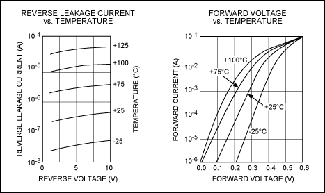
Figure 5. Typical Schottky diode data-sheet parameters.
This will probably fix the hot-start issue. To test it, find a voltage reference that fails at a given temperature. Bring the output of the voltage reference out of the oven. A short piece of coax works well if there is an RF pickup. The 20pF of a foot of coax is not an issue at DC. Measure the voltage-reference output with the voltage reference off. Note the negative voltage (sometimes there are two ESD diodes in series inside the IC). Let's say it is -1V. Next, connect a silicon diode (like the 1N4747) to clamp the voltage at 0.6V. Does the reference start? Put two Schottky diodes in series (0.52V at room temperature). Does the reference start? Put one Schottky diode in the circuit (0.24V at room temperature). Now does the reference start? Heat the Schottky or put it in the oven—does the reference start? By progressively trying the startup limits is a good way to understand the starting margin.
The result of adding the Schottky diode reduces the amount that the reference output can be pulled below ground. As the temperature rises, the Schottky diode's forward voltage drops, alleviating the issue. The tests proved that adding the Schottky diode protects the voltage reference from the negative voltage, and allows it to start at high temperature.
POR is used in several ways to ensure proper operation. For example, the Analog MAX6029 voltage reference is based on a bandgap-reference cell. Here, the reference stabilizes only at the proper operating voltage. As we discussed in the With Bandgap References section, the bandgap will balance and be stable at two points: the design current and the zero current. This is absolutely necessary to make sure the part starts and avoids the zero-current condition, so designers spend significant time simulating the circuits with voltage, temperature, and process variations. In the MAX5134 quad 16-bit digital-to-analog converter (DAC), the POR function initializes the part to a known condition. The MAX5134 can reset to zero or midscale. Depending on the application, this is an important system-safety factor. If a motor is being controlled, someone could be in danger if random movement was allowed during power-up. This hardware POR is independent of any software control and allows safe operation, until the system software can take over accurate control. Furthermore, POR operates in a MAX5482 nonvolatile digital potentiometer. Systems such as fiber communication and power supplies require calibration during final production test. The MAX5482 allows the memorizing of one of 1024 different tap or voltage points. POR automatically recalls the calibration setting as the power supply turns on.
Conclusion
Self-starting can be hard to do, whether it is self-starting humans, cold automobiles, or ICs. PORs ensure that systems start in known and safe states. At times, the IC manufacturer's engineers can help a customer when they use a part in a way that was never intended by the design engineers. For best results, manufacturers recommend adhering to the data-sheet parameters for the obvious reason: those were the parameters that the IC designer used to create the device.


