Using Safety Application Notes to Aid Safety Designs—Part 1: Getting Started
Using Safety Application Notes to Aid Safety Designs—Part 1: Getting Started
2026年05月04日
要約
Among Analog Devices’ industrial functional safety (FS) portfolio are the FS-enabled parts, whose safety application notes are publicly accessible on their product pages. These safety application notes provide a component's FS information such as failure rate, failure mode distribution (FMD), and pin failure mode and effects analysis (FMEA). Such notes also give system integrators easy access to important information to aid their safety-related system design. For this reason, this first part of the series discusses the recommended sanity checks system integrators need to do before using a component's safety application note.
Introduction
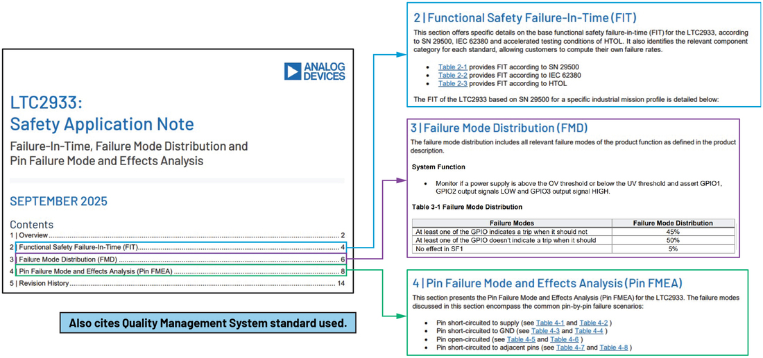
The Know Your Safety Application Notes series1,2,3 from Analog Devices gives an overview of the safety application notes for ADI functional safety (FS) integrated circuits (ICs)—non-FS-compliant devices or standard products recommended for FS applications due to their functions, features, and extensive user experience. As shown in Figure 1, ADI’s safety application notes detail a component’s development process, its failure rate prediction calculated from three reliability prediction methods, failure mode distribution (FMD) in terms of the IC’s system function(s), and its pin failure mode and effects analysis (FMEA) covering short-to-supply, short-to-ground, short-to-adjacent pins, and open-pin failures.
This second article series about ADI’s safety application notes aims to guide system integrators in using these notes to aid their technical safety analyses. Furthermore, this first part focuses on the next step system integrators need to take when using a safety application note for their ADI component.
Checking the Conditions Used for Reliability Predictions
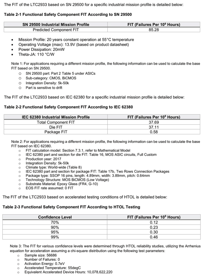
ADI’s safety application notes provide reliability predictions based on three methods: failure rate calculated by using SN29500, IEC 62380, and the Arrhenius equation by using high temperature operating life (HTOL) data. For each reliability prediction method shown in Figure 2, notes exist under the tables summarizing the calculated failure rate to show the conditions used. This includes information like mission profile, operating voltage, power dissipation, thermal specification based on the package used, confidence level in the case of Arrhenius HTOL, and other reliability prediction method required inputs that can be derived from a product’s data sheet as well as design-related data like integration density, technology structure, etc. This information is made available so system integrators who are familiar with reliability predictions can recalculate an IC’s failure rates at their own convenience when operating conditions assumed in the initial calculations are different. Part 1 of the Know Your Safety Application Notes shows where ADI’s reliability database can be found as well as offers insights into how to change the confidence level of a reliability prediction. If similar conditions are used and the assumed conditions are directly applicable, then system integrators can readily use the safety application note’s reliability predictions data.
Checking the Conditions Used for FMD
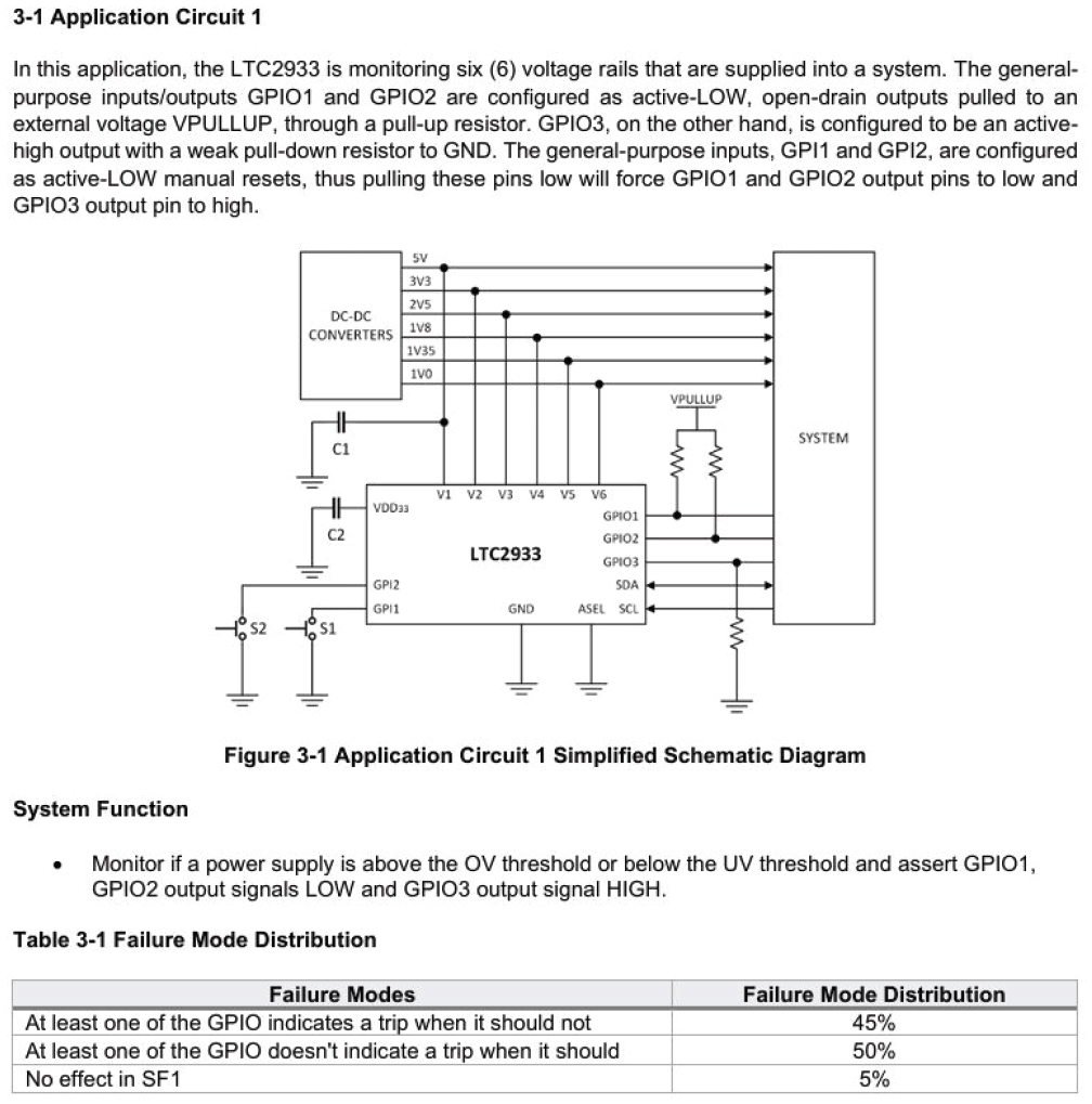
Aside from system function, the FMD section of an ADI safety application note also shows the application circuit assumed. This is shown in Figure 3. It is important that system integrators check whether the IC used in their application is like the assumed application circuit. Otherwise there may be some modifications that need to be made in the analysis. For instance, looking at Figure 3, perhaps you are only using four of the six LTC2933 channels.
Checking the Conditions Used for the Pin FMEA
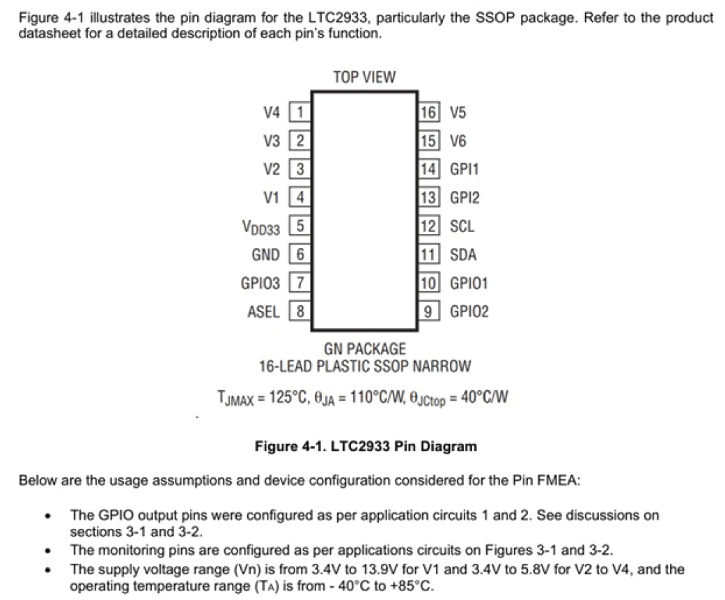
The pin FMEA section of a safety application note, as shown in Figure 4, shows the component’s package used, the assumed device configuration and device configuration, and the tables showing the analysis. System integrators need to ensure that a similar pinout arrangement and device configuration as per application circuit assumed is used so they can use such analysis in their design.
In some cases, additional diagnostics or other safety measures may be available at the system level that the analysis at ADI did not assume.
Post-Sanity Check Activities
After having a run of sanity checks for the safety application note, system integrators may either find that the information is readily applicable in their application or they may find some needed modifications. In case the latter is true, they may reach ADI through ADI Support Channels.
Conclusion
In summary, ADI’s FS-enabled ICs’ safety application notes serve as a vital resource for system integrators, providing granular reliability data and failure analysis necessary to aid FS design. However, the effectiveness of these documents depends on a diligent sanity check process, where integrators must verify that the mission profiles, application circuits, and pin configurations assumed in the notes align with their specific system requirements. By confirming these conditions—or reaching out to ADI for further technical support when discrepancies arise—engineers can help ensure that the failure rates and FMD data they integrate into their safety analysis are both accurate and robust, ultimately leading to more reliable industrial safety-related systems.
著者について
Bryan Angelo
この記事に関して
製品
製造中
EEPROMを内蔵したプログラム可能な6電圧スーパーバイザ
新規設計に推奨
0.3%高精度デュアル・チャンネル監視回路
製造中
高電圧、過電圧/低電圧、保護スイッチコントローラ
高精度、可変パワーリミッタ
RF リニア電圧レギュレータ、1.2 A、固定出力、超低ノイズ、高 PSRR
ロードダンプ/逆電圧保護回路
ロードダンプ/逆電圧保護回路
超小型、過電圧保護/検出回路
コンデンサ可変のリセットおよびウォッチドッグタイムアウト内蔵、125nA nanoPower監視回路
低電力、シングル/デュアル電圧ウィンド検出器
低電力、シングル/デュアル電圧ウィンド検出器
高電圧、低電流電圧モニタ、SOTパッケージ
低電力、シングル/デュアル電圧ウィンド検出器
低電圧、高精度、シングル/デュアル/トリプル/クワッド電圧µP監視回路
産業向けソリューション


