Avoid Design Misinterpretations that Put System Operation in Jeopardy
要約
Humans are unusual creatures because sometimes partial knowledge, ego, and misplaced confidence are more dangerous than no knowledge of a subject. With electronic design, misinterpretations and misunderstandings can lead to circuits that fail to function as expected. To an inexperienced designer, some circuits look like they should work. Meanwhile, the experienced engineer cringes, wondering how someone can get themselves in such a fix. This application note presents three case studies that illustrate how some simple analysis and a proper understanding of the laws of physics can educate designers to avoid similar issues in future designs.
Introduction
When digital designers confront analog systems, misinterpreting device operation or design requirements results in some fascinating analog "horror" stories. Sometimes digital designers misunderstand how a part works (or should work), so they make strange assumptions that result in misusing the part. Sadly, as a general rule, today's engineering schools concentrate on digital technology while almost totally ignoring analog design. As a result inexperienced digital engineers have to learn analog by trial and error. Some of the resulting devices would make Rube Goldberg proud.¹
This article considers a few horror stories from an analog engineer's viewpoint. Several common digital misunderstandings reveal some analog truths: the importance of clean power and grounds; impedance DC-level matching can be ignored when connecting circuit stages; and perhaps most importantly, ignoring the laws of physics will eventually cause system failure.
It Was Beautiful on the Surface, but...
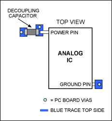
A data sheet says, "Place the power-supply decoupling capacitors as close to the IC's power pin as possible." As one can see in Figure 1, the designer did just that!

Figure 1. A printed circuit board (PCB) layout showing IC and capacitor.
Other components were around the Figure 1 IC, but these were the most important. It was a four-layer board with signal traces on the outer two layers. An experienced analog engineer would expect the power and ground planes on the inner two planes, respectively. In fact, this circuit was intended to function as a mixed-signal board in a video application. It had high-frequency analog-to-digital converters (ADCs) and digital-to-analog converters (DACs) with signal-processing circuits. The component density was just moderate. There were no ball-grid-array (BGA) packages requiring more layers to complicate the layout.
When testing the design, we found that the video output was noisy, actually very noisy. We traced most of the noise to one IC. Figure 1 shows the layout on the top side of the board. There was a huge noise signal on the power pin. When a thin wire was placed through the "ground" side via of the decoupling capacitor and the connection followed to the other side of the board, there was a trace (not an internal ground plane) that disappeared into another via. This configuration was definitely troublesome. By reviewing the board layout program here, we can highlight the desired node and view all the connections. Figure 2 is part of what was found.

Figure 2. Board layout viewed using the PCB design software.
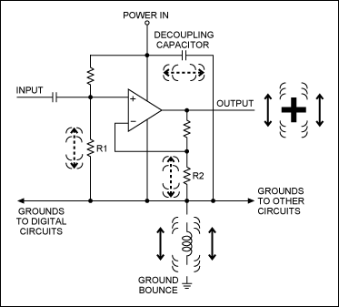
The traces looked like they were done by a digital circuit autorouter. This was indeed the case because the board layout designer was inexperienced with analog. There were no internal ground and power planes. (See application note 4345, "Well Grounded, Digital Is Analog," for grounding tips and proper use of planes.) To the inexperienced designer, the circuit looks correct because all grounds are connected together. That approach is true at DC; but at operating frequencies, the equivalent circuit has many parasitic elements, as shown in Figure 3.

Figure 3. A way to visualize ground bounce in the circuit.
Each trace and via of Figure 2 contains resistance and inductance. In Figure 3, those distributed parasitic components are collapsed into the single series inductor near the ground at the lower center of the diagram. Picture the inductor in your mind's eye as a mechanical coil spring. The IC is drawn here as an operational amplifier to simplify the explanation, but it could be any circuit.
The noise of the digital and other circuits to the left and right above the ground bounce symbol are moving the voltage up and down when the currents in the other circuits change state. The analog signal is, therefore, contaminated at several points:
- The noise is applied to the op amp input through R1.
- The noise is applied to the ground pin of the op amp. (Yes, there is a power supply rejection ratio (PSRR) specification, but that uses ground as the reference. This means that the noise is directly added to the output signal.)
- The noise is applied to the op amp input through R2.
- The noise is applied to the op amp input through the decoupling capacitor and the resistor above R1.
Remember that a capacitor is a two-way device. The decoupling capacitor's job is to homogenize the high frequencies on both sides of the capacitor. If there is noise on the voltage bus and the ground is a clean, low-impedance return path to the power supply, then a decoupling capacitor can help reduce the noise. However, if the ground has high impedance and lots of noise, the decoupling capacitor actually adds noise to the voltage bus.
The noise added at various points around the op amp in Figure 3 makes a real mess at the output because the noise signals are added with phase differences. All the noise tends to add at the output, as indicated by the bouncy plus symbol. The output is also plagued by the effect of small nonlinearities in the op amp. The noise is multiplied by the various nonlinearities of various elements, thus creating sum and difference harmonics which splatter the noise all over the spectrum.
The design fix was a simple explanation of how to make good ground and power planes (You do not want to see the power traces in the original design—they were equally problematic.) Once the inexperienced engineer and layout person understood the concepts, the next layout had no noise problems.
An Analog Radio with an Impossible Layout
A problem was discovered on a radio-transceiver evaluation board. A designer took the schematic and entered it into a printed circuit board (PCB) autorouter designed for digital logic. The resulting board was unusable as a radio; there was no ground plane—and it did indeed qualify as another Rube Goldberg design.
The critical signal paths on the board were scattered, stitched through vias (inductors), and power was not decoupled properly. Then the antenna on the board was a strange shape. It is hard enough to design a straight line antenna. The designer was asked about the software program used to make such an antenna. We expected to hear about the discovery of a "great new antenna-design software tool," but the designer said, "that was the space left so that is where we put the antenna."
Although the designer was a good microprocessor engineer, he had no idea that antenna size is controlled by the signal wavelength. He also had no concept of a ground plane being the other half of the antenna. A more knowledgeable radio engineer in another group saved that design.
Does This Resonate with You?
Musical instruments and radios utilize resonance to operate. Figure 4 shows pipes of a pipe organ. Each is pipe is tuned to a specific musical note. When we tune a radio from one station (frequency) to another, resonance helps us select one station and reject all others.

Figure 4. A pipe organ located in a church in Berne, Indiana, U.S.
Radio antennas sizes are tuned to resonate at specific frequencies, but therein lies the problem. While working on an automotive project, a designer wanted to have long-distance communication by placing an antenna inside the engine compartment of an automobile. This was an aftermarket product that needed to transmit and receive under the metal hood of the engine compartment of any car.
The designer thought that the engine compartment of the cars would form a resonate cavity at one specific frequency and amplify the signal. Unfortunately, resonate cavities require exacting design and since each car type has different size engine compartment, resonance was hard to achieve. Additionally, the designer did not want to pay automotive prices for high-temperature-qualified components.
By not understanding that engine compartments were hot, the designer had wrongly expected consumer-grade parts with maximum temperature ratings of 70°C to survive. An experienced radio engineer was called to fix the design.
Minimizing Noise with Digital and Analog Grounds
The MAX541 16-bit DAC combines analog and digital in the same package: analog ground and digital ground pins. The device's data sheet explains how to connect them and use star points for the ground planes.
The terms for ground can be misleading. Instead of analog and digital, clean and dirty might be better descriptions. As explained in application note 4345, "Well Grounded, Digital Is Analog," digital circuits can ignore some noise because of the threshold effect. Analog circuits cannot ignore that noise. In the case of data converters care must be used to connect the digital and analog grounds. This is especially true when systems comprise many ADCs and DACs; skill and experience are required to connect the ground planes in a star configuration. Additionally, the analog and digital planes need to be cross-connected at each data converter. The objective here is to have the major currents return to the power supply with little current in the cross-connects. Expert engineers can use resistors, ferrite beads, or inductors for cross-connects to direct currents as a function of frequency. Experience allows one to minimize the number of board layouts, but the only way to be sure is to empirically and iteratively optimize the circuit layout and reduce the noise issues.
Conclusion
Unfortunately, all parts can be misused and abused. Experience is also a wonderful teacher. Most of the time hindsight allows us to improve a design as we wonder why we failed to see the obvious sooner.
In the end, no part can do everything for every design and every designer. That is a good lesson. No matter how much Rube Goldberg tried, a single contraption of his could not incorporate every part in every application. That is a good thing, because people have enjoyed Rube's many cartoons for generations.


