AN-2579: The Design of the Inverting Buck/Boost Converter Topology

要約

The inverting buck/boost converter topology is an often mysterious and misunderstood category of DC-DC converters. This document attempts to remove any misconception around the circuit by providing a step-by-step design procedure with equations, schematics, simulations, and considerations to ensure that the circuit is properly designed.

Introduction

The inverting buck/boost topology is useful for converting a positive input to a negative output. It is an alternative to the Ćuk topology when a compact solution is desired. The inverting buck/boost topology converts an input voltage to either a lower voltage (buck mode) or higher voltage (boost mode). However, unlike the Ćuk topology, the inverting buck/boost converter produces more noise at the output. Therefore, it generates more electromagnetic content. The inverting buck/boost converter is often derived from the buck converter by swapping output and ground references. Therefore, it is often improperly labeled inverting as if it is the only topology that can invert an input or inverting buck as if it is the only topology that can invert and step down to a negative output. The reality is that the inverting buck/boost topology, like the Ćuk topology, can invert but it can also step down or step up a voltage. The inverting buck/boost converter can be asynchronous if a diode is used and synchronous if the diode is replaced with a metal-oxide semiconductor field-effect transistor (MOSFET), which provides higher efficiency. The inverting buck/boost converter topology is generally used for applications that require up to 150 W.

Operation

The operation of the inverting buck/boost converter is shown in Figure 1 and in Figure 2.

Figure 1. On-Time State.

Figure 1. On-Time State.

During the on-time state, the MOSFET is on and the diode is off. The inductor is energized by the input.

Figure 2. Off-Time State.

Figure 2. Off-Time State.

During the off-time state, the MOSFET is off and the diode is on. The inductor is de-energized by the load at the output.

The operation for Figure 1 and Figure 2 uses a diode, which makes the circuit asynchronous. The diode can be replaced with a MOSFET, which makes the circuit synchronous.

Design Approach

To properly design the inverting buck/boost converter, it is important to consider the operation at each extreme of the input voltage: high line (highest input voltage) and low line (lowest input voltage). Inductance and output capacitance are functions of several parameters. This document describes the conditions that yield the minimum inductance and minimum output capacitance to satisfy the specifications for a target application. The process is sequential. Therefore, designing across the input voltage range allows the engineer to take into account all the critical parameters that allow proper operation.

Design Specifications

The specifications for the inverting buck/boost converter are as follows:

Vin(max) = 72 V

Vin(min) = 36 V

VOUT = −48V

IOUT = 2 A

ƒS = 350 kHz

ΔIOUT_TRA(25%) = 500 mA

ΔVOUT_SS(1%) = 480 mV

ΔVOUT_TRA(1%) = 480 mV

Design Objectives

The objective of this document is to provide guidance through an entire design cycle. For example, consider the targets listed in the Design Specifications section for a specific application, such as a telecommunication platform, where −48 V outputs are not uncommon. It is assumed that a high voltage, high power, and high efficiency solution is required. Because the output of the inverting buck/boost converter is −48 V, the converter is in buck mode when the input voltage is between +72 V and +48 V and it is in boost mode when the input voltage is between +36 V and +48 V. Both buck and boost modes are presented and repetition is intentional for additional clarity. Some numbers are rounded up or down.

Buck Mode Design Procedure

The following example uses the LTC3896 controller IC and shows continuous conduction mode (CCM) operation in buck mode, which is the condition when the output voltage is lower than the input voltage. Figure 3 shows the circuit and Figure 4 shows the startup at high line.

Figure 3. LTC3896 Inverting Buck/Boost Converter in Buck Mode (+72 V to −48 V Conversion)

Figure 3. LTC3896 Inverting Buck/Boost Converter in Buck Mode (+72 V to −48 V Conversion)

Figure 4. Waveforms at Startup (VIN = 72 V).

Figure 4. Waveforms at Startup (VIN = 72 V).

The output power is calculated as follows:

Equation 1.

The current through the inductor is the sum of the input current through the top MOSFET and the output current through the bottom MOSFET. Unlike the buck topology, which is rated by the output current, the inverting buck/boost topology is rated by the peak current through the MOSFET in an asynchronous converter or the top MOSFET in the synchronous counterpart.

The average input current is the average current through the top MOSFET.

Equation 2.

where η is the estimated efficiency in buck mode.

The average current through the top MOSFET during the on-time state is equal to the average current through the inductor and the average current through the bottom MOSFET during the off-time state.

Equation 3.

The maximum current ripple through the inductor is calculated as follows:

Equation 4.

where 0.55 is equivalent to a 55% inductor current ripple. This current swing is a function of the average current through the inductor and, depending on current levels for the application and inductor saturation currents, it typically ranges between 40% and 80%.

The top MOSFET used in the circuit is an Infineon Technologies BSC520N15NS3, 150 V, 21 A transistor which has a maximum RDS(ON) of 52 mΩ. An average of 3.404 A flows through it during the on-time state. Therefore, the voltage drop across the device is calculated as follows:

Equation 5.

Equation 6.

The minimum duty cycle is as follows:

Equation 7.

where VQ2 is the voltage drop across the bottom BSC520N15NS3 MOSFET with 3.404 A of current through it.

Equation 8.

The period is as follows:

Equation 9.

On-time and off-time are calculated as follows:

Equation 10.

Equation 11.

The minimum inductance can be calculated at high line, which is when the voltage across the top MOSFET is largest, the duty cycle is smallest and the on-time is smallest.

Equation 12.

= 44 μH → 47 μH

A Würth Elektronik 7443634700, 47 µH, 12.2 mΩ inductor is selected.

The load resistance is calculated as follows:

Equation 13.

The minimum output capacitance for steady state at high line is calculated as follows:

Equation 14.

However, to compensate for any sudden increase or decrease of load current at the output, additional capacitance is needed.

The inverting buck/boost converter has a unique feature called the right half plane zero (RHPZ). It is part of its transfer function and it limits the bandwidth of the converter. Its lower frequency occurs at low line and maximum load, which results in the largest duty cycle and the smallest load resistance. However, when the converter operates in buck mode with the highest input voltage (smallest duty cycle), the RHPZ moves to a higher frequency and it is located at:

Equation 15.

To ensure the stability of the inverting buck/boost converter, it is recommended to reduce its bandwidth to 25% to 33% of the RHPZ location.

Equation 16.

The minimum output capacitance for a 25% load transient and 1% overshoot/undershoot is calculated with as follows:

Equation 17.

Eight TDK C5750X7S2A106K230KB, 10 µF, 100 V, 2220 ceramic capacitors, which derate to 4.415 µF at 48 V DC, are used in parallel at the output to reduce the impedance. Unfortunately, due to the output being −48 V, high-voltage capacitors must be selected. In addition, the capacitors must provide a sufficient amount of capacitance under bias. Therefore, eight relatively large ceramic capacitors are used (2220). This choice is a tradeoff between solution size and output ripple voltage. Using a hybrid solution, such as electrolytic and ceramic capacitors, is also an option and a single electrolytic capacitor in combination with a single ceramic capacitor can be used. However, because electrolytic capacitors feature a relatively high equivalent series resistance (ESR) and equivalent series inductance (ESL), the hybrid option increases the output ripple voltage at the switching frequency in the steady state.

The maximum ripple current through the inductor, shown in Figure 5, is calculated as follows:

Equation 18.

Figure 5. Inductor Ripple Current (VIN = 72 V).

Figure 5. Inductor Ripple Current (VIN = 72 V).

The current through the inductor is the sum of the input current through the top MOSFET and the output current through the bottom MOSFET.

The peak current through the top MOSFET, inductor, and bottom MOSFET is calculated by the following:

Equation 19.

The current through the top MOSFET has a trapezoidal shape and its RMS value is calculated by the following:

Equation 20.

The RMS current for the bottom MOSFET can be calculated in the same way using Equation 20 but replacing DMIN with 1 − DMIN.

The RMS current is the root mean square of the input DC and AC currents multiplied by the duty cycle.

The output ripple voltage is a combination of two terms.

Equation 21.

The first term is produced by the capacitive component of the output capacitor.

Equation 22.

The second term is produced by the resistive component of the output capacitor, the ESR.

Equation 23.

where 358 µΩ is the combined ESR at the switching frequency of the output capacitors.

Combining the terms gives the total output ripple voltage, which is shown in Figure 6.

Figure 6. Output Ripple Voltage (VIN = 72 V).

Figure 6. Output Ripple Voltage (VIN = 72 V).

Equation 24.

Either the first term or the second term can dominate over the other.

If ΔVC dominates over ΔVESR, the output looks triangular.

If ΔVESR dominates over ΔVC, the output looks trapezoidal.

In this case, ΔVC is larger than ΔVESR. Therefore, the output looks triangular.

The RMS output ripple current through the capacitor has a trapezoidal shape.

Equation 25.

Therefore, a set of eight capacitors with a combined RMS current rating of at least 1.638 A must be selected.

The overshoot/undershoot at high line is shown in Figure 7 and it is estimated by the following:

Equation 26.

Figure 7. Load Regulation for 2 A → 2.5 A →2 A (VIN = 72 V).

Figure 7. Load Regulation for 2 A → 2.5 A →2 A (VIN = 72 V).

Boost Mode Design Procedure

The following example uses the LTC3896 controller IC and shows CCM operation in boost mode which is the condition when the output voltage is higher than the input voltage. Figure 8 shows the circuit and Figure 9 shows the startup at low line.

Figure 8. LTC3896 Inverting Buck/Boost Converter in Boost Mode (+36 V to −48 V Conversion)

Figure 8. LTC3896 Inverting Buck/Boost Converter in Boost Mode (+36 V to −48 V Conversion)

Figure 9. Waveforms at Startup (V<sub>IN</sub> = 36 V).

Figure 9. Waveforms at Startup (VIN = 36 V).

The output power is calculated as follows:

Equation 27.

The current through the inductor is the sum of the input current through the top MOSFET and the output current through the bottom MOSFET.

The average input current is the average current through the top MOSFET.

Equation 28.

where η is the estimated efficiency in boost mode.

The average current through the top MOSFET during the on-time state is equal to the average current through the inductor and the average current through the bottom MOSFET during the off-time state.

Equation 29.

The maximum current ripple through the inductor is calculated as follows:

Equation 30.

The top MOSFET used in the circuit is an Infineon Technologies BSC520N15NS3, 150 V, 21 A transistor which has a maximum RDS(ON) of 52 mΩ. An average of 4.807 A flows through it during the on-time. Therefore, the voltage drop across the device is as follows:

Equation 31.

Equation 32.

The maximum duty cycle is as follows:

Equation 33.

where VQ2 is the voltage drop across the bottom BSC520N15NS3 MOSFET with 4.807 A of current through it.

Equation 34.

The period is as follows:

Equation 35.

On-time and off-time are as follows:

Equation 36.

Equation 37.

The minimum inductance can be calculated at low line, which is when the voltage across the top MOSFET is smallest, the duty cycle is largest and the on-time is largest.

Equation 38.

= 22.2 μH → 47 μH

A Würth Elektronik 7443634700, 47 µH, 12.2 mΩ inductor is imposed to satisfy the inductance requirement for the high line condition.

The load resistance is as follows:

Equation 39.

The minimum output capacitance for steady state at low line is as follows:

Equation 40.

However, to compensate for any sudden increase or decrease of load current at the output, additional capacitance is needed.

The inverting buck/boost converter features an RHPZ. It is part of its transfer function and it limits the bandwidth of the converter. Its lower frequency occurs at low line and maximum load, which results in the largest duty cycle and the smallest load resistance.

Equation 41.

To ensure the stability of the inverting buck/boost converter, it is recommended to reduce its bandwidth to 25% to 33% of the RHPZ location.

Equation 42.

The minimum output capacitance for a 25% load transient and 1% overshoot/undershoot is given by the following:

Equation 43.

Eight TDK C5750X7S2A106K230KB, 10 µF, 100 V, 2220 ceramic capacitors, which derate to 4.415 µF at 48 V, are used at the output.

Therefore, an effective capacitance of 35.32 µF is selected to satisfy the low line condition.

The minimum ripple current through the inductor, shown in Figure 10, is given by the following:

Equation 44.

Figure 10. Inductor Ripple Current (VIN = 36 V).

Figure 10. Inductor Ripple Current (VIN = 36 V).

The current through the inductor is the sum of the input current through the top MOSFET and the output current through the bottom MOSFET.

The peak current through the top MOSFET, inductor, and bottom MOSFET is given by the following:

Equation 45.

The current through the top MOSFET has a trapezoidal shape and its RMS value is given by the following:

Equation 46.

The RMS current for the bottom MOSFET can be calculated in the same way by using Equation 46 but replacing DMAX with 1 − DMAX.

The RMS current is the root mean square of the input DC and AC currents multiplied by the duty cycle.

The output ripple voltage is a combination of two terms.

Equation 47.

The first term is produced by the capacitive component of the output capacitor.

Equation 48.

The second term is produced by the resistive component of the output capacitor.

Equation 49.

where 358 µΩ is the combined ESR at the switching frequency of the output capacitors.

Combining the terms gives the total output ripple voltage, which is shown in Figure 11.

Figure 11. Output Ripple Voltage (VIN = 36 V).

Figure 11. Output Ripple Voltage (VIN = 36 V).

Equation 50.

Either the first term or the second term can dominate over the other.

If ΔVC dominates over ΔVESR, the output looks triangular.

If ΔVESR dominates over ΔVC, the output looks trapezoidal.

In this case, ΔVC is larger than ΔVESR. Therefore, the output looks triangular.

The RMS output ripple current through the capacitor has a trapezoidal shape.

Equation 51.

Therefore, a set of eight capacitors with a combined RMS current rating of at least 2.323 A must be selected.

The overshoot/undershoot at low line is shown in Figure 12 and it is estimated by the following:

Equation 52.

Figure 12. Load Regulation for 2 A → 2.5 A → 2 A (VIN = 36 V).

Figure 12. Load Regulation for 2 A → 2.5 A → 2 A (VIN = 36 V).

LTpowerCAD

If an LTpowerCAD model for an IC in the inverting buck/boost configuration is available, the software helps the designer to produce a design, and tuning of the circuit that meet the requirements listed in the Design Specifications section. Based on the desired crossover, the software suggests a resistor/capacitor combination used for the compensator to achieve an appropriate dynamic load regulation response. However, LTpowerCAD models are not always available. At the time of the writing of this document, the LTC3896 is supported in LTpowerCAD. Figure 13 and Figure 14 show an example for the LTC3896 design discussed in this document.

Figure 13. LTpowerCAD Setup for the LTC3896 (First Tab Features Design)

Figure 13. LTpowerCAD Setup for the LTC3896 (First Tab Features Design)

Figure 14. LTpowerCAD Setup for the LTC3896 (Third Tab Features Compensation)

Figure 14. LTpowerCAD Setup for the LTC3896 (Third Tab Features Compensation)

LTspice

LTspice models are available for a majority of Analog Devices, Inc., switch-mode power supplies (SMPSs) and they are useful for a first approximation in the time and the frequency domains. Setting up the converter directly in LTspice can lead to recursive and time-consuming simulations. An LTspice simulation allows approximate bandwidth of the converter. A parametric sweep of the resistor/capacitor combination used for the compensator at specific input and output conditions can be performed to further tune the loop.

Compensation

Unless internally compensated, most inverting buck/boost circuits require external compensation. This translates to a compensator that typically includes an operational transconductance amplifier (OTA), current-mode control (CMC) and Type II compensation. Whether through software or mathematics, the end goal of compensation is to select a resistor/capacitor pair which produces a zero that allows acceptable stability over the input voltage range.

If neither LTpowerCAD nor LTspice can be used, mathematics is the only option.

When it comes to compensation, the recommended approach is to calculate the lowest location of the RHPZ which occurs at low line.

Equation 53.

Next, assume a crossover around ¼ of the RHPZ.

Equation 54.

Then, place a zero at 10% to 30% of the potential crossover.

Equation 55.

Finally, select the values of RC and CC to insert the zero for the error amplifier.

Equation 56.

Although not always necessary, a pole can be placed to cancel the RHPZ or the zero produced by the output capacitors or to suppress noise.

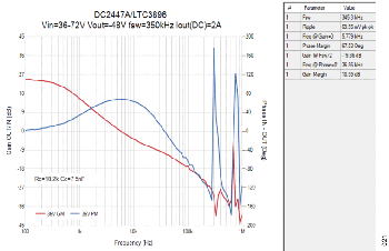
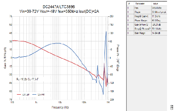
The final choice for the location of the zero is made at low line where the bandwidth is smallest. A Bode plot can reveal whether the RC and CC combination is optimal. After testing the LTC3896 at the bench, the optimal choice of RC is 18.2 kΩ and CC remained 7.5 nF. Therefore, the zero at 1.166 kHz is near 18% of the initial estimated bandwidth (6.4 kHz) or near 20% of the actual bandwidth (5.779 kHz).

Notes

The following is a series of observations that the designer must consider before building the inverting buck/boost circuit:

  • The inductance is calculated at high line, whereas the capacitance at the output is calculated at low line.
  • The maximum ripple current through the inductor occurs at high line, whereas the maximum ripple voltage at the output occurs at low
  • The circuit is designed at each extreme of the input voltage To meet current and voltage ripple requirements, use a 47 µH inductor and 35.32 µF of effective capacitance at the output.
  • It is customary to add a small high-frequency capacitor from the positive input to the negative output to compensate for the top MOSFET
  • If the design is asynchronous, the voltage drop across the bottom MOSFET, VQ2, can be replaced by VD, the equivalent drop across the diode for a specific average current.


Test Data

This section presents results for the LTC3896 inverting buck/boost circuit captured at the bench at low line and high line. R7, D1, and R8 are not added to the printed circuit board (PCB).

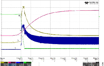
Figure 15. Startup, VIN = +36 V, VOUT = −48 V, IOUT = 1.5 A
Figure 18. Startup, VIN = +72 V, VOUT = −48 V, IOUT = 1.5 A
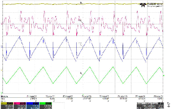
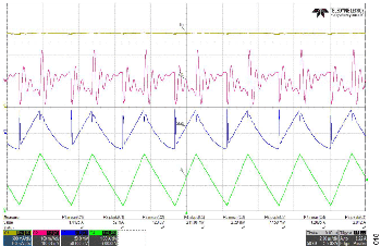
Figure 16. Steady State, VIN = +36 V, VOUT = −48 V, IOUT = 2 A
Figure 19. Steady State, VIN = +72 V, VOUT = −48 V, IOUT = 2 A
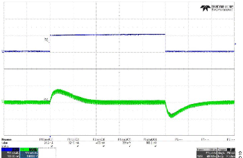
Figure 17. Load Regulation, VIN = +36 V, VOUT = −48 V, IOUT = 2 A (DC) + 0.5 A (AC)
Figure 20. Load Regulation, VIN = +72 V, VOUT = −48 V, IOUT = 2 A (DC) + 0.5 A (AC)
Figure 21. Loop Analysis, VIN = +36 V, VOUT = −48 V, IOUT = 2 A
Figure 23. Loop Analysis, VIN = +72 V, VOUT = −48 V, IOUT = 2 A
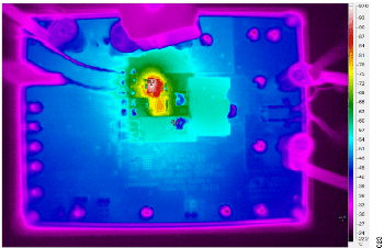
Figure 22. Thermal Analysis, VIN = +36 V, VOUT = −48 V, IOUT = 2 A (No Air Flow)
Figure 24. Thermal Analysis, VIN = +72 V, VOUT = −48 V, IOUT = 2 A (No Air Flow)

Considerations

The following considerations must be made when designing an inverting buck/boost converter:

  • Proper components selection. The voltage rating for the input/output capacitors must be appropriate to compensate for the bias applied to them. The voltage rating for the MOSFETs must be at least VIN(MAX) + |VOUT|. For an asynchronous design, the current rating for the diode must be at least ISW(MAX) and the voltage rating for the diode must be at least VIN(MAX) + |VOUT| to allow operation in reverse The inductor must be selected to avoid saturation and rated with a current above the peak inductor current.
  • Enabling and level shifting. Unless the inverting buck/boost converter is always enabled, level shifting the enable pin is necessary and schemes can be introduced to address the issue. Varieties of options are available and a simple circuit with only one binary junction transistor (BJT) of the PNP type or one MOSFET of the positive channel (PMOS) type and three resistors accomplish the task. In some cases, level shifting is taken care of internally, such as in the case of the LTC3896 IC.
  • Input capacitance. The RMS current that appears at the input of the converter and the RMS current through the top MOSFET have the same shape. They are also close in magnitude. The RMS current value calculated for the top MOSFET helps in the process of selecting the right combination of input capacitors to avoid excessive component stress. An LTspice simulation at maximum RMS current can reveal the actual RMS current spread across each capacitor as a function of its own impedance.
  • Switching frequency. Choosing the optimal switching frequency helps to achieve the right balance between conduction losses and switching losses while trading off smaller or larger inductance with smaller or larger output capacitance.
  • Compensation. The RHPZ reduces the bandwidth of the converter and compensation must be tuned at low line in boost mode. If a model of the converter is available in LTpowerCAD, the tuning process can be faster. If not, zeros and poles for the compensator are placed mathematically and load regulation can be verified in LTspice. If the output capacitors are entirely of the ceramic type, it is not necessary to add a high-frequency capacitor to cancel the zero produced by the output capacitors and their combined ESR.
  • Loop analysis. Phase margin (PM) and gain margin (GM) must be verified across the line from high to nominal to low to maintain about 60° of PM and at least −6 dB of GM both at ½ the switching frequency and where the phase crosses 0° (LTpowerCAD, in the third tab for compensation of the LTC3896, tries to enforce −6 dB and −8 dB, respectively, when the GM figures are not met). Bode plots must be captured similarly to a buck converter, as shown in Figure 25, by using a 10 Ω to 49.9 Ω resistor. However, for the inverting buck/boost converter, because its output is negative, the AC injection into the feedback of the IC must be done across a resistor placed below R2 (near 0 V). The grounds of the input probes of the frequency response analyzer must float with respect to the input power supply and system ground. A cheater plug is sufficient to address the floating requirement. However, in this case, because the output is −48 V, a 10:1 attenuation is required to avoid damaging the inputs of the frequency response analyzers, which typically do not tolerate more than about ±15 V. Therefore, the cheater plug can be avoided and high voltage differential probes with attenuation can be used.

Figure 25. R9 Is Used for AC Injection to Generate Bode Plots

Figure 25. R9 Is Used for AC Injection to Generate Bode Plots

  • Capacitors between positive input and negative output. One or more capacitors can be placed across input and output to compensate for the high-frequency switching of the top MOSFET. Typically, the amount of capacitance is For dynamic load regulation, the capacitance can be increased in value which helps reducing the output voltage deviations (undershoot/over-shoot) that occur when output loading changes abruptly. The value of capacitance must be a small fraction of the output capacitance. The voltage rating of the capacitors must be larger than VIN(MAX) + |VOUT| and derating must be considered, especially for high-voltage applications.
  • Output capacitance. Mathematically, increasing output capacitance reduces the output ripple voltage but it also reduces the loop Therefore, overloading an output rail with capacitance is not recommended because it can be counterproductive. For accurate calculations and results, DC bias must be considered. For more accurate results, AC bias can be introduced (AC bias is the output ripple voltage, which is added to the output regulated voltage). DC and AC biases add by superposition.
  • Load regulation. The ability of the inverting buck/boost converter to regulate the output when a sudden load change occurs can be tested by appending a MOSFET at the output of the circuit. The drain must be connected to the system ground, the source must be connected to the negative output and the gate can be pulsed with a function generator that must float with respect to the input power supply and system ground. A cheater plug is sufficient to solve the floating requirement.
  • Filtering. Additional output filtering may be necessary to clean up the electromagnetic content produced by switching at the output, which is coupled with the inevitable existence of ESL, especially when electrolytic capacitors are introduced and high voltages are required at the output. Additional LC filters influence the stability and operation of the switcher. Three-terminal capacitors are useful and powerful options. They provide low impedance at the switching frequency and suppress noise as well as reducing layout space. However, their voltage rating is relatively low so they are not suited for medium to high voltage applications. Tuning the switching frequency to match the lowest output impedance provides the optimal output ripple voltage solution.
  • Output voltage clamping. If necessary, the output can be clamped by a Schottky diode which avoids excessive positive excursion between negative output and ground during startup. The diode must be placed between the nodes with the anode on the negative side and the cathode on the ground side.
  • Power delivery limitations. Although the converter delivers full power at high line, in some cases, load current must be reduced to avoid excessive peak current at the switching node, which can damage the MOSFETs, especially for monolithic solutions. Controllers such as the LTC3896 are less constrained by current peaks because they allow flexibility in choosing MOSFETs that are external to the IC.
  • Probing. It is important to probe signals such as switching nodes and output rails by using proper techniques. A pair of twisted wires terminating at a probe connector such as the Tektronix 131-0258-00 shown in Figure 26 can be mated with a passive voltage probe. The setup helps in reducing the amount of unwanted parasitic inductance that can magnify voltage spikes and ringing during transient events. This setup also reduces the amount of mechanical stress across components such as capacitors. Other alternatives that can be considered, if space allows, are shown in Figure 27 and include SubMiniature Version A (SMA) and U.FL connectors that can be mated with Bayonet Neill-Concelman (BNC) connectors directly at the oscilloscope inputs.

Figure 26. Tektronix 131-0258-00 Probe Connector.

Figure 26. Tektronix 131-0258-00 Probe Connector.

Figure 27. SMA, U.FL, and BNC Connectors.

Figure 27. SMA, U.FL, and BNC Connectors.

  • Layout. Some PCBs host buck converters and can be reconfigured to work as inverting buck/boost converters. However, in some cases, reconfiguring the buck converter output to the ground plane and the ground plane to the negative output causes abnormal and erratic behavior at the bench, which is undesirable because it can be confusing and time-consuming. The best approach is to create a layout tailored specifically for the inverting buck/boost topology rather than adapting a PCB with a buck converter. This is for the best performance and low noise operation. Component placement must also be considered to reduce the amount of stray capacitance or inductance. The importance of a good layout must never be underestimated. Figure 28 shows the layout for the standard DC2447A demo board.

Figure 28. Layout for the DC2447A Demo Board that Hosts the LTC3896 Controller

Figure 28. Layout for the DC2447A Demo Board that Hosts the LTC3896 Controller

Summary

The inverting buck/boost topology is useful for generating negative voltage rails.

Although it can seem intimidating, the methodology outlined and the considerations listed in this document enable a designer to produce a circuit that can be simulated in software and tested at the bench. Software tools like LTpowerCAD and LTspice can help in designing and tuning the inverting buck/boost converter but the engineer can resort to pure mathematics to find a solution.

参考資料

Basso, Christophe. Switch-Mode Power Supplies. The McGraw-Hill Companies, Inc., 2008.

Kessler, Matthew. AN-1083 Application Note. Designing an Inverting Buck Boost Using the ADP2300 and ADP2301 Switching Regulators. Analog Devices, 2010.

Yang, Ricky. AN-1168 Application Note. Designing an Inverting Power Supply Using the ADP2384/ADP2386 Synchronous Step- Down DC-to-DC Regulators. Analog Devices, 2010.

Young, Sam. Signal Level Shifting with μModule Regulator for Positive-to-Negative Inverting Applications. Analog Devices, 2015.

著者

Enrico Reineri

Enrico Reineri

Enrico Reineri received his B.S.C.E. from California State University Northridge in 2005 and his M.S.E.E. from San José State University in 2010. He worked for International Rectifier, Texas Instruments and Juniper Networks. Enrico joined Analog Devices in August 2018 and since then he has worked on a variety of topologies of DC/DC converters. He is currently a senior applications engineer with the High Performance Power group in San José, CA, U.S.A.