TMC6140
新規設計に推奨Low voltage BLDC motor driver 5 to 30V, for external N-channel MOSFETs, integrated lowside chargepump for low RDSon at low battery voltage
- 製品モデル
- 2
- 1Ku当たりの価格
- 価格は未定
製品情報
- 3-phase motors up to 100 A coil current (external MOSFETs)
- Voltage Range 5 to 30 V DC
- Gate Drive 0.5 A or 1.0 A
- 3V3 Switching Regulator (0.5 A) with internal Schottky diode (up to 100 mA)
- Diagnostics output via UART-TxD
- Charge pump pin to utilize buck converter for step-up converter
- 3 Bottom Shunt Amplifiers
- Analog programmable short detect
- 2 Low Power Modes with 0.25 mA standby current consumption Applications
TMC6140 is a fully integrated universal 3-phase MOSFET gate driver for PMSM servo or BLDC motors. External MOSFETs for up to 100 A motor current are supported. Three bottom shunt amplifiers allow easy current sensing and enhanced commutation of the motor. A switching regulator (3.3 V, 0.5 A, internal Schottky diode for up to 100mA) generates enough power for the IOs and the micro controller. Further on, it can serve as step-up converter to stabilize statically the gate voltages of the MOSFETs. A DIAG output for further diagnostics and two different power down modes are available.
APPLICATIONS:
- Industrial Drives
- Power Tools
- Robotics
- Textile Machines
- Factory Automation
- Laboratory Automation
- Pumps
- Fans
- Battery Operated Devices
ドキュメント
データシート 1
| 製品モデル | ピン/パッケージ図 | 資料 | CADシンボル、フットプリント、および3Dモデル |
|---|---|---|---|
| TMC6140-LA | LFCSP | ||
| TMC6140-LA-T | LFCSP |
これは最新改訂バージョンのデータシートです。
ソフトウェア・リソース
必要なソフトウェア/ドライバが見つかりませんか?
ドライバ/ソフトウェアをリクエストツールおよびシミュレーション
設計ツール 1
評価用キット
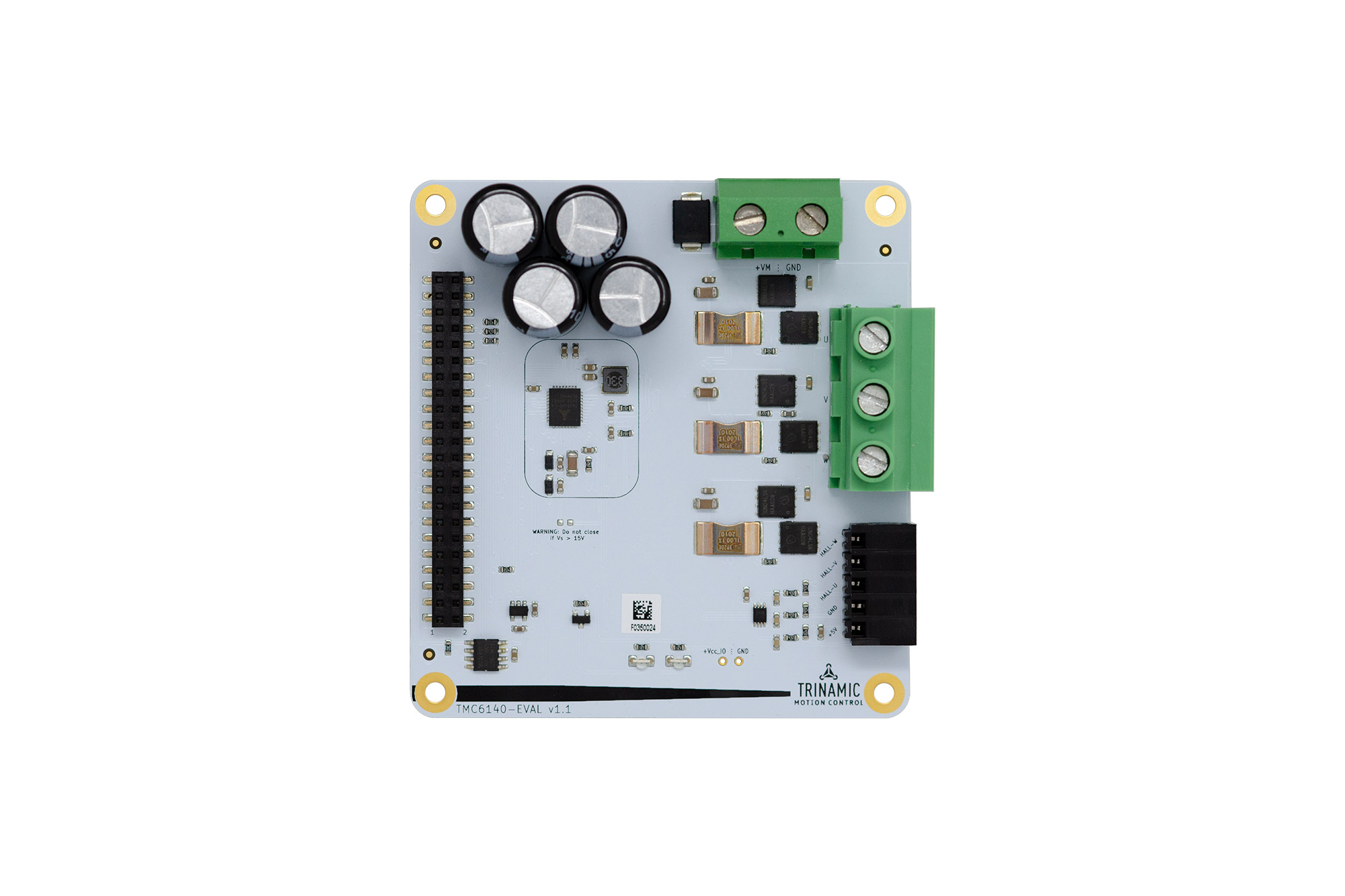
Evaluation Board for TMC6140