MAX20358

新規設計に推奨

Wearable Power-Management Solution

利用上の注意

本データシートの英語以外の言語への翻訳はユーザの便宜のために提供されるものであり、リビジョンが古い場合があります。最新の内容については、必ず最新の英語版をご参照ください。

なお、日本語版のデータシートは基本的に「Rev.0」(リビジョン0)で作成されています。そのため、英語版が後に改訂され、複数製品のデータシートがひとつに統一された場合、同じ「Rev.0」の日本語版のデータシートが異なる製品のデータシートとして表示されることがあります。たとえば、「ADM3307E」の場合、日本語データシートをクリックすると「ADM3311E」が表示されます。これは、英語版のデータシートが複数の製品で共有できるように1本化され、「ADM3307E/ADM3310E/ADM3311E/ADM3312E/ADM3315E」(Rev.J)と改訂されたからで、決して誤ってリンクが張られているわけではありません。和文化されたデータシートを少しでも有効に活用していただくためにこのような方法をとっておりますので、ご了解ください。

アナログ・デバイセズ社は、提供する情報が正確で信頼できるものであることを期していますが、その情報の利用に関して、あるいはその利用によって生じる第三者の特許やその他の権利の侵害に関して一切の責任を負いません。また、アナログ・デバイセズ社の特許または特許の権利の使用を明示的または暗示的に許諾するものでもありません。仕様は予告なしに変更する場合があります。本紙記載の商標および登録商標は、各社の所有に属します。

Viewing:

製品情報

  • Extend Time Between Charges
    • 3 x Nano-IQ, 400mA Buck Regulators (IQ = 400nA typ)
    • 0.500V to 1.130V in 10mV Steps
    • 0.500V to 2.075V in 25mV Steps
    • 0.500V to 3.650V in 50mV Steps
  • 2 x Micro-IQ LDO/Load Switches (IQ = 1μA typ)
    • 1.71V to 5.5V Input-Voltage Range
    • 100mA Output-Current Capability
    • 0.900V to 4.0V in 100mV Steps
  • Nano-IQ Fast Transient LDO (IQ = 820nA typ)
    • Optimized for use with Sensor AFEs
    • 1.71V to 5.5V Input-Voltage Range
    • 100mA Output-Current Capability
    • 0.900V to 4.075V in 25mV Steps
  • Nano-IQ Real-Time Clock LDO (IQ = 200nA typ)
    • Always-On Configurable for RTCs in μC Timers
    • 1.2V [+25mV, +50mV] and 1.8V [+25mV, +50mV]
  • Micro-IQ Buck-Boost Regulator (IQ = 2μA typ)
    • 1.5W Output
    • 2.6V to 5.5V in 50mV Steps
    • Dynamic Voltage Scaling
  • 3 x Nano-IQ, Low On-Resistance Load Switches (IQ = 260nA typ)
    • Low 0.25Ω (typ) On-Resistance
    • Short-Circuit Protection
    • Soft-Start Feature
  • Easy-to-Implement Li+ Battery Charging
    • Wide Fast Charge Current Range: 4mA to 500mA
    • +28V/-5.5V Tolerant Input
    • Programmable JEITA Current/Voltage Profiles
    • Programmable Automatic Step-Charging
  • Seamless Interaction with MAX20361 Solar Energy Harvester
  • Multiple-Purpose Control Pins are Provided for Flexible Control
  • Minimize Solution Footprint Through High Integration
    • Programmable Push-Button Controller
    • Programmable Supply Sequencing
    • Battery Seal Shipping Mode
    • On-Chip Voltage/Charge Current Monitor Mux

The MAX20356 is a highly integrated and programmable power-management solution designed for ultra-low-power wearable applications. It is optimized for size and efficiency to enhance the value of the end product by extending battery life and shrinking the overall solution size. A flexible set of power-optimized voltage regulators including multiple buck converters, a buck-boost converter, and linear regulators provide a high level of integration and the ability to create a fully optimized power architecture. The quiescent current of each regulator is ultra-low to extend battery life in always-on applications.

The MAX20356 includes a complete battery-management solution with battery seal, charger, power path, and fuel gauge. Both thermal management and input protection are built into the charger. The device also includes a factory-programmable button controller with multiple inputs that are customizable to fit specific product user requirements.

A low-noise, 1.5W buck-boost converter provides highly efficient and clean power conversion required for the LEDs used in optical heart-rate systems such as PPG and SPO2 measurements. The MAX20356 is also equipped with a nano IQ fast transient LDO, optimized for use in analog front-end (AFE) sensors. The MAX20356 is configurable through an I2C interface that allows for programming various functions and reading the device status, including the ability to read temperature and supply voltages through the monitor multiplexer.

The MAX20356 is available in a 63-bump, 0.5mm pitch, 3.71mm x 4.48mm, wafer-level package (WLP) and operates over the −40°C to +85°C extended temperature range.

Applications

  • Wearable Devices
  • IoT

MAX20358
Wearable Power-Management Solution
MAX20356 Simplified Block Diagram MAX20356 Pin Configuration
myAnalogに追加

myAnalogの製品セクション(通知受け取り)、既存/新規プロジェクトに製品を追加する。

新規プロジェクトを作成
質問する
サポート

アナログ・デバイセズのサポート・ページはアナログ・デバイセズへのあらゆるご質問にお答えするワンストップ・ポータルです。


ドキュメント

さらに詳しく
myAnalogに追加

myAnalogのリソース・セクション、既存/新規プロジェクトにメディアを追加する。

新規プロジェクトを作成

ソフトウェア・リソース

必要なソフトウェア/ドライバが見つかりませんか?

ドライバ/ソフトウェアをリクエスト

評価用キット

eval board
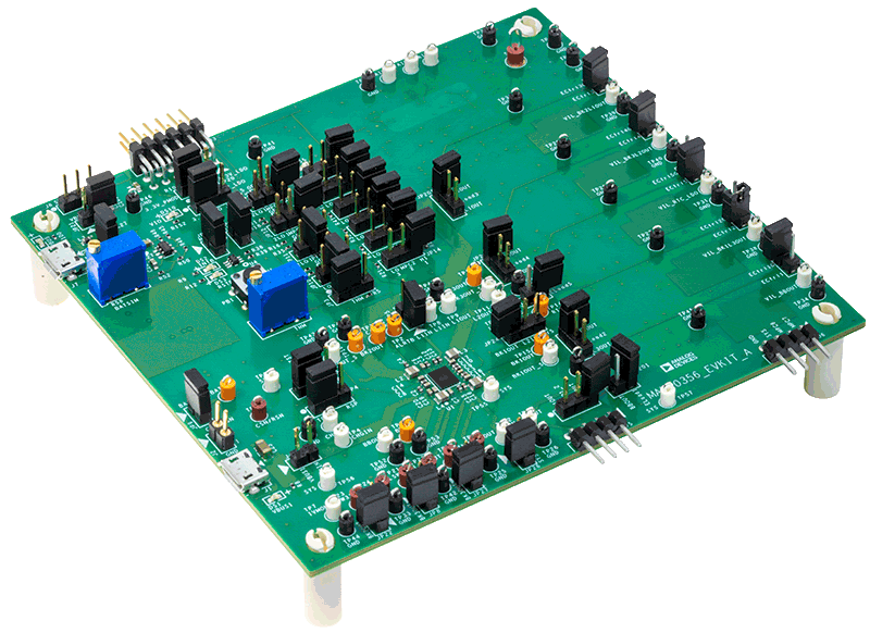
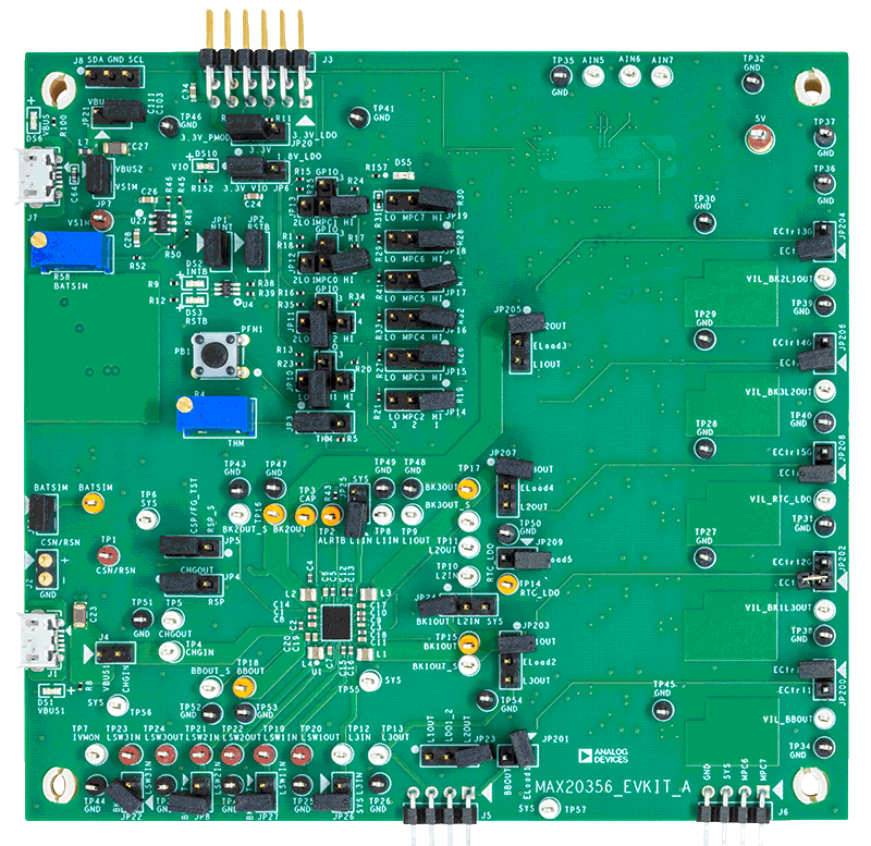
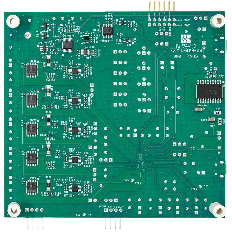
MAX20356EVKIT

MAX20356の評価用キット

機能と利点

  • USB給電オプション
  • 柔軟な設定
  • 内蔵バッテリ・シミュレーション
  • 出力電圧測定用の検出テスト・ポイント
  • Windows® 8/Windows 10互換のグラフィカル・ユーザ・インターフェース(GUI)ソフトウェア
  • 完全実装および試験済み

製品詳細

MAX20356評価用キット(EVキット)は、超低消費電力ウェアラブル・アプリケーション向けに設計されたMAX20356パワー・マネジメント・ソリューションを評価するための、組み立て済み、試験済みの回路です。

3つの降圧コンバータ、1つの昇降圧コンバータ、4つのリニア電圧レギュレータ(RTC LDO含む)、3つの負荷スイッチなど、一連の電力最適化済みの柔軟な電圧レギュレータにより、高度な集積化が実現し、完全に最適化された電源アーキテクチャを構築できます。デバイスの動作と機能の詳細については、MAX20356 ICのデータシートを参照してください。

このデバイスは、各種機能のプログラミングとデバイス・ステータスの読み取りを可能にするI2Cインターフェースを介して設定できます。このEVキットのGUIアプリケーションがMAXPICO2PMB#アダプタ・ボードにコマンドを送信し、デバイスを設定します。

このEVキットにはMAX20356 EVキット・バージョンのICが標準で搭載されています

MAX20356EVKIT
MAX20356の評価用キット
MAX20356EVKIT Board Photo Angle MAX20356EVKIT Board Photo Top MAX20356EVKIT Board Photo Bottom

最新のディスカッション

MAX20358に関するディスカッションはまだありません。意見を投稿しますか?

EngineerZone®でディスカッションを始める

最近表示した製品