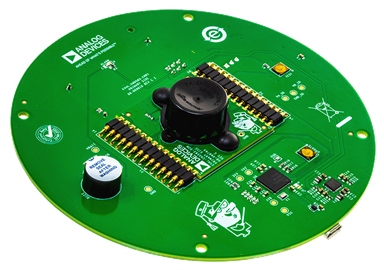
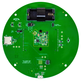
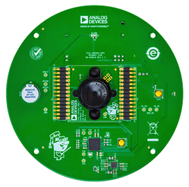
Overview
Design Resources
Design & Integration File
- Schematic
- Bill of Materials
- Gerber Files
- Assembly Drawing
- Allegro Project File
Evaluation Hardware
Part Numbers with "Z" indicate RoHS Compliance. Boards checked are needed to evaluate this circuit.
- ADSW-SMOKEALGO-PRODLIC ($27500.00) ADPD188BI Smoke Detection Algorithm
- ADSW-SMOKEDATA-PRODLIC ($11000.00) ADPD188BI Smoke Detection Dataset
- EVAL-CN0583-CRR1 ($80.00) Carrier Board
- EVAL-CN0583-SOM ($50.00) Multistandard Micropower Verified Smoke Detector Solution
Device Drivers
Software such as C code and/or FPGA code, used to communicate with component's digital interface.
MAX32660 GitHub no-OS Driver Source Code
Features & Benefits
The CN0583 reference design plus related software is designed and tested to meet UL 217 8th edition, EN14604:2005, and similar smoke/fire detection standards. To address the needs of different customers, a number of solution offerings are available which are summarized in the table below.
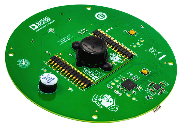
The hardware is designed to accelerate prototyping and the evaluation of the embedded smoke detection algorithm. The hardware is comprised of the EVAL-CN0583-SOM and EVAL-CN0583-CRR1 Carrier Board.
The Data package (ADSW-SMOKEDATA-PRODLIC) provides an extensive (1000+) smoke dataset taken at UL 217 and EN14604 certified facilities for those who wish to develop their own algorithm. It includes the CN0583 source code for initialization, calibration, environmental compensation, data pre-processing - but excludes the detection algorithm.
The Algorithm package (ADSW-SMOKEDATA-PRODLIC) includes everything in the Data package and adds UL & EN validated smoke detection algorithm and associated algorithm project files.
- Complete Smoke Detector System on Module
- Micropower Operation for >10 Year Battery Lifetime
- UL 217 & UL 268 Verified Smoke Detector Algorithm
- EN 54-7 & EN 14604 Verified Smoke Detector Algorithm
Documentation & Resources
-
CN0583 User Guide12/4/2023WIKI
Circuit Function & Benefits
Since the 1970s, smoke detectors have become commonplace in commercial and residential buildings. Two basic types of detectors exist today: the oldest technology is the ionization type that uses radioactive material to ionize the air and checks for an electrical imbalance, the second, newer technology is the photoelectric type that uses a light source aimed at an angle away from a photodetector (PD) and checks for photodetector current caused by the light reflecting from airborne particles to the photodiode. Between two types, the photoelectric smoke detector enjoys greater popularity due to its improved reliability in detecting common house fires and faster response times to smoldering fires.
Until recently, smoke detector technology and regulations have also remained virtually the same despite advances in electronics and common household materials throughout the decades. New revisions in standards, such as ANSI/UL 217 8th edition and ANSI/UL 268 7th edition, published by Underwriters Laboratory (UL) and the NFPA® 72 National Fire Alarm Code, published by the National Fire Protection Agency (NFPA), aim to address this gap by updating the requirements for modern smoke detector designs. Other worldwide standards, such as ISO 7240 is likely to add similar tests to address this and other concerns in the future, making it more important to have advanced sensing capabilities and software-driven detection algorithms that can be adjusted to meet new requirements.
Fundamentally, these new regulations aim to reduce the incidents wherein a user may disable the smoke detector due to false alarms. Disabled smoke detectors lead to fire related deaths, so by reducing false alarms, smoke detectors are less likely to be manually disabled. New smoke detectors are required to tolerate a minimum quantity of nuisance smoke without alarming and must last 10 years on the installed battery.
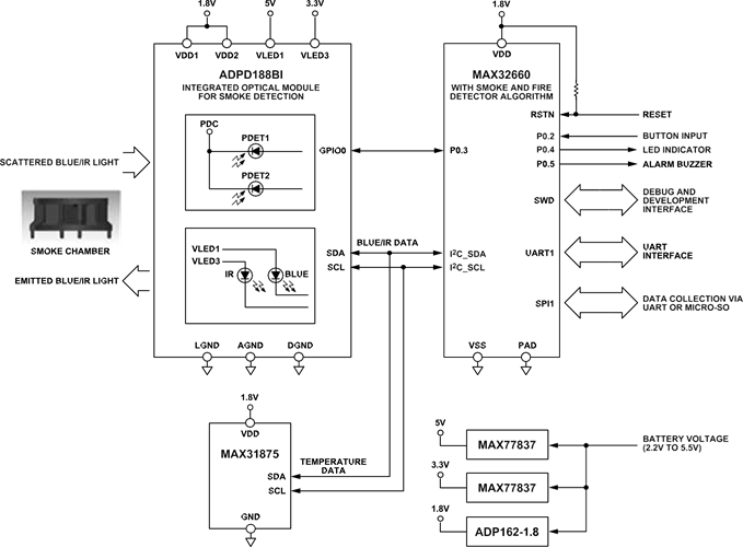
The circuit shown in Figure 1 is a tested and verified smoke detector system-on-module (SOM) reference design with an available algorithm and data set. This system includes all of the components needed for standalone operation such as an on-board optical sensor, microcontroller, temperature sensor, and power regulators. The design of the SOM features castellated pins that allow it to be fitted into a carrier board or soldered directly to a custom application board for test and development.
Embedded software and algorithms are used to evaluate smoke and fire tests specified in UL 217 (8th Edition), UL 268 (7th Edition), and EN 54-7/EN 14604 standards. These algorithms and data sets are available separately to help deploy your smoke detection solution faster. For customized algorithmic developments, additional data can be collected and added into the algorithm to adapt it for other standards.

Circuit Description
SMOKE DETECTION USING THE ADPD188BI
The ADPD188BI optical module is a complete photometric system specifically designed for smoke detection applications. Using the ADPD188BI in place of traditional, discrete smoke detector circuits greatly simplifies the design by incorporating the optoelectronics (consisting of two LEDs and two photodetectors) and the analog front end (AFE) into the package.
To perform smoke detection, the ADPD188BI utilizes a dual wavelength technique: two integrated LEDs emit light at two different wavelengths. One LED emits at 470 nm (blue light) and the other LED at 850 nm (infrared light). These LEDs are pulsed in two independent time slots, and the transmitted light is scattered back onto the photodetectors by particulate matter in the air, as illustrated in Figure 2.

Two integrated photodetectors then receive the scattered light and produce proportional output currents, which are converted internally by the AFE into digital code. Assuming the LED optical power is kept constant, an increase in ADPD188BI output values over time indicates an increase or buildup in airborne particles.
UL 217 & EN 14604 SMOKE AND FIRE TEST ALGORITHM
The 8th edition UL 217 standard requires detectors to respond to six different types of fire and smoke within a specific window of time and obscuration (as measured by a reference obscuration meter). Table 1 lists the obscuration percentage and response time requirements for each UL 217 test.
| TEST | UL 217 8th Edition | ||
| Type | Name | Sec. Num. | Result |
| Wind Tunnel | Sensitivity | 42 | Pass |
| Wind Tunnel | Directionality | 43 | Pass |
| Wind Tunnel | Velocity-Sensitivity Test | 44 | Pass |
| Wind Tunnel | Variable Ambient (0°C & 49°C) | 62 | Pass |
| Wind Tunnel | Humidity | 63 | Pass |
| Fire | Paper Fire | 51.2 | Pass |
| Fire | Wood Fire | 51.3 | Pass |
| Fire | Flaming polyurethane Foam Test | 51.4 | Pass |
| Fire | Smoldering Smoke Test | 52 | Pass |
| Fire | Smoldering Polyurethane Foam Test | 53 | Pass |
| Fire | Cooking Nuisance Smoke Test | 54 | Pass |
| Fire | Go/No Go Flaming Polyurethane Foam Test | 54 | Pass |
The EN14604:2005 standard states a detector needs to respond to four different types of fire and smoke within a specific window of time, obscuration (as measured by a reference obscuration meter) and relative change in measuring ionization chamber (MIC) reading (as measured by a reference MIC). Table 2 lists the smoke density and response time requirements for each EN14604 test. For more information, including ordering, please visit the algorithm and data page.
| TEST | EN 14604 | EN 54-7 | |||||
| Type | Name | Sec. Num. | Result | Sec. Num. | Result | ||
| Wind Tunnel | Directional dependence | 5.3 | Pass | 4.3.2 | Pass | ||
| Wind Tunnel | Reproducibility | 5.4 | Pass | 4.3.3 | Pass | ||
| Wind Tunnel | Air movement | 5.5 | Pass | 4.4.1 | Pass | ||
| Wind Tunnel | Dazzling | 5.6 | Pass | 4.4.2 | Pass | ||
| Wind Tunnel | Dry Heat | 5.7 | Pass | 5.7.1.2 | Pass | ||
| Wind Tunnel | Cold | 5.8 | Pass | - | Pass | ||
| Wind Tunnel | Damp | 5.9 | Pass | 5.7.2.1 | Pass | ||
| Fire | (TF5) Flaming Liquid | 5.15 | Pass | - | Pass | ||
| Fire | (TF4) Flaming Polyurethane | 5.15 | Pass | - | Pass | ||
| Fire | (TF3) Smoldering Cotton Fire | 5.15 | Pass | - | Pass | ||
| Fire | (TF2) Smoldering Wood Fire | 5.15 | Pass | - | Pass | ||
| Fire | (TF8) Low Temperature Black Smoke | NA | NA | - | Pass | ||
| Fire | (TF1) Open Wood Fire | NA | NA | - | Fail | ||
The ADSW-SMOKEALGO-PRODLIC algorithm was specifically designed for detecting fire conditions using the ADPD188BI sensor and Accumold® 28800x smoke chamber, as defined by the UL 217 and EN54-7/EN14604 standards. The algorithm itself was tuned and verified through a large data set, ADSW-SMOKEDATA-PRODLIC captured from many ADPD188BI devices across all the test scenarios defined in Table 1. The tests were performed at certified OSHA approved laboratories specializing in fire and life safety. The data set includes reference measurements to quantify sensor performance and alarm conditions for different smoke sources. An example smoke profile is shown in Figure 3, where the IR and blue sensor measures are compared against the reference smoke obscuration data under the Hamburger and Polyurethane test scenario.
Because battery powered devices are a common use case for smoke detectors, the ADSW-SMOKEALGO-PRODLIC was designed and built to minimize the output data required from the ADPD188BI, along with the number of microcontroller computations necessary while still meeting the strict UL 217 and EN54-7/EN14604 standards. For more details on the testing validation, see the test results.

CALCULATING THE POWER TRANSFER RATIO
The smoke response of the ADPD188BI is best expressed as a ratio of the received optical power to the transmitted optical power. Referred to as the power transfer ratio (PTR), this parameter is a much more meaningful value than the raw output codes, as it is independent of the actual hardware settings used. Additionally, obscuration level, the standard unit of measurement for smoke detectors, is directly related to the PTR, as shown in Equation 1:

where:
- PTR is the power transfer ratio in nW/mW.
- γ is the ADPD188BI scaling factor (0.64 typical for blue light and 0.24 typical for infrared light).
- β is the obscuration level in ft-1.

Figure 4. Typical LED PTR and Obscuration During Polyurethane Fire Event
For each LED, the PTR can be calculated using Equation 2:

where:
- PTR is the power transfer ratio of the LED in nW/mW.
- IPD is the photodetector current in nA.
- ILEDx_PK is the peak LED current in mA.
- RPD is the photodetector responsivity in A/W (0.26 typical for blue light and 0.41 typical for infrared light).
- ηLEDx is the LED efficiency in W/A.
CALCULATING THE ILED AND IPD
The ADPD188BI allows for configuring the peak currents of each LED through a combination of course and fine adjustment registers and a current scale factor. The peak LED current can be calculated using Equation 3 to Equation 6:

where:
- ILEDx_PK is the peak LED current in mA.
- ILEDx(COARSE) is the LED coarse current in mA.
- ILEDx(FINE) is the LED fine current in mA.
- ILEDx(SCALE) is the LED current scaling in mA.
ILEDx_COARSE, ILEDx_FINE, and ILEDx_SCALE are the values for the control registers for each LED.
Note that in the ADPD188BI registers, the blue LED is referred to as LED1 and the infrared LED is referred to as LED3.
The photodetector current is calculated using the ADPD188BI digital output, as shown in Equation 7:

where:
- IPD is the photodetector current in nA.
- Code is the 32-bit output code in LSB.
- Q is the ADC resolution in nA/LSB.
- PULSE_COUNT is the number of LED pulses for the time slot.
The ADC resolution of the ADPD188BI is dependent on the setting of the LED pulse width and the setting of the internal transimpedance amplifier (TIA) gain. Refer to the ADPD188BI data sheet for the ADC resolution using different TIA gain values.
READING THE ADPD188B1 GAIN AND INTERCEPT CALIBRATION VALUES
The ADPD188BI LEDs have a wide initial tolerance on both gain and intercept. To account for this variation, a set of gain and offset coefficients are measured during production test and written to nonvolatile memory. Calibration coefficients are calculated by using Equation 8 to Equation 14:

For the blue LED:

For the infrared LED:

Note: These calibration equations are valid for devices with Module ID 33. For the calibration equations for devices with Module ID 30 and Module ID 31, refer to AN-2033.
LED Temperature Compensation
The LED loop response of the ADPD188BI is affected by the ambient temperature. Figure 5 and Figure 6 illustrate the temperature effect on the IR and Blue LED, respectively, across the ADPD188BI operating temperature range at common LED current settings.v
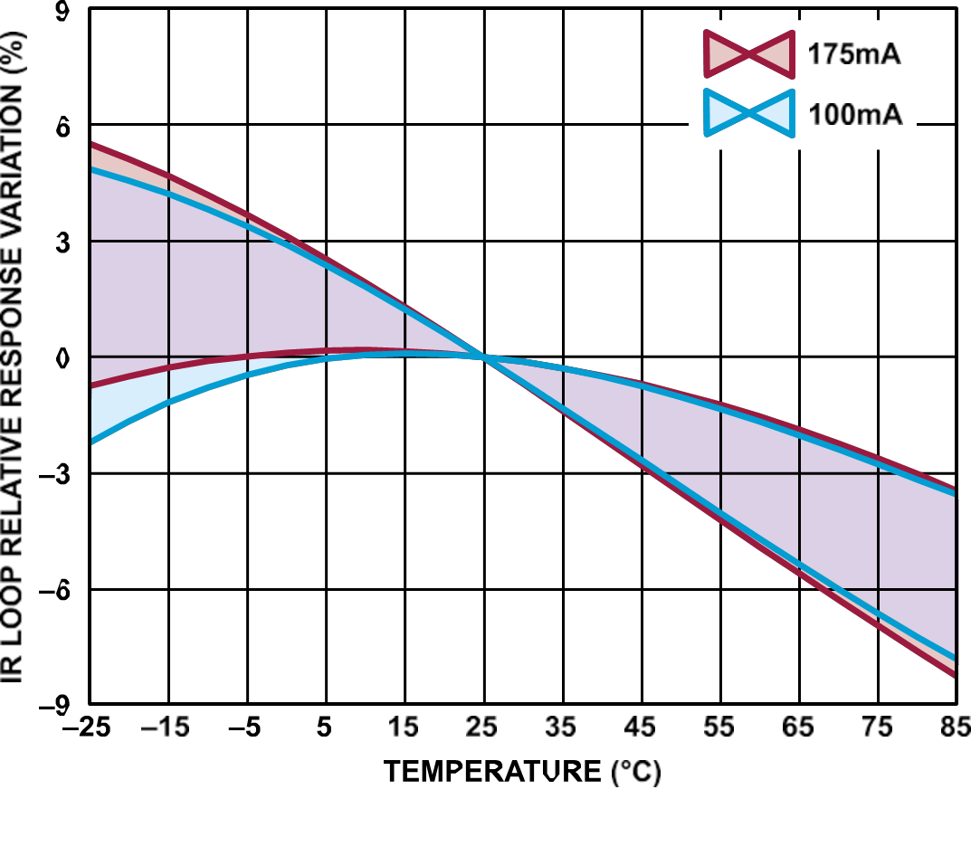
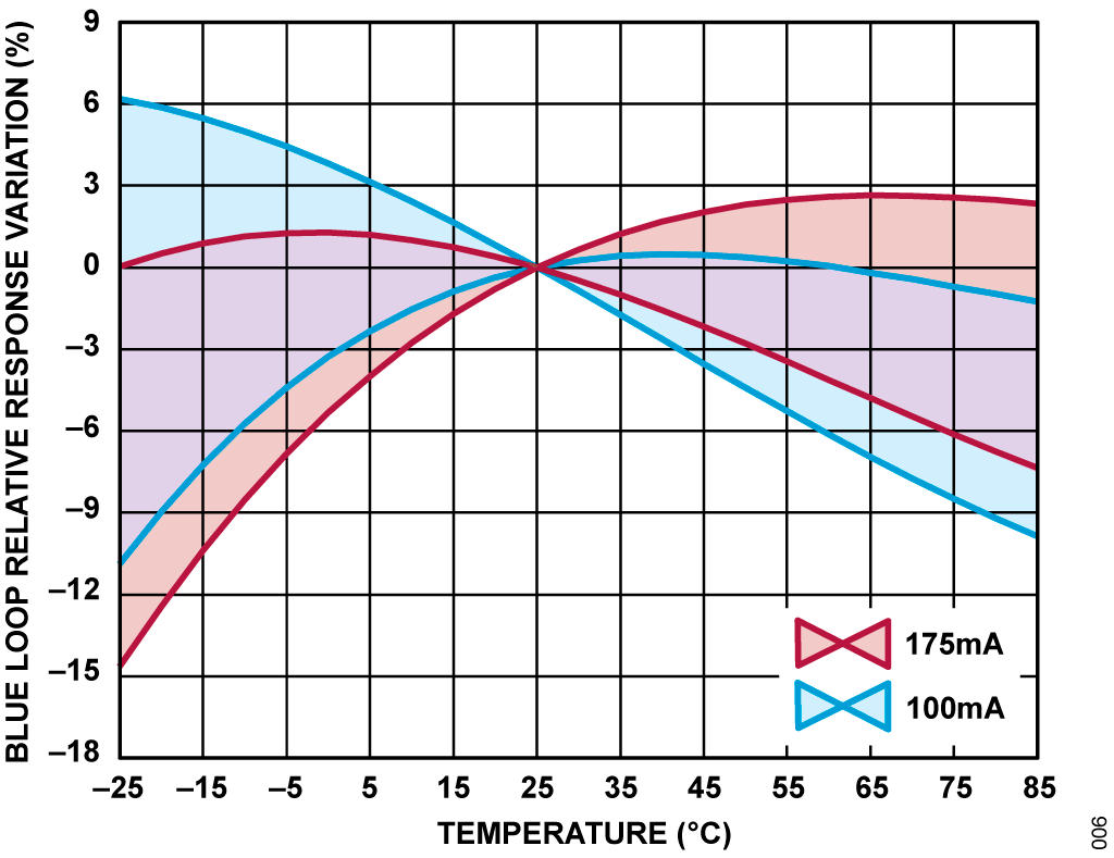
To determine the value of the relative response, the ability to measure the ambient temperature in real time is required. Compensation for the temperature effect can then be done by dividing the ADPD188BI output by the relative response for the current ambient temperature, taken from the appropriate curve in Figure 5 and Figure 6.

where:
- Relative ResponseT is the relative response at the current ambient temperature.
- CodeT is the output code at the current ambient temperature.
- Code25°C is the output code at temperature 25°C.
To obtain the most accurate measurement, it is highly recommended to place the temperature sensor as close as possible to the ADPD188BI. However, since space is at a premium inside the chamber, the size of the sensor is the primary consideration. The CN0583 SOM uses a MAX31875 digital temperature sensor next to the ADPD188BI to monitor the temperature inside the smoke chamber. With an extremely tiny WLP package size that measures only 0.84 mm x 0.84 mm x 0.35 mm, this device is ideal for providing temperature monitoring capabilities to space-constrained hardware like the CN0583 SOM. The only external components required for its operation are a decoupling capacitor for the supply pin, and I2C pull-up resistors. The accuracy of the MAX31875 is rated ±1°C when measuring temperatures between 0°C to 70°C.
USING A SMOKE CHAMBER WITH THE ADPD188BI
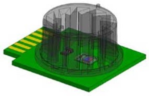
Most smoke detector solutions available in the market use smoke chambers to help reject ambient light, reduce internal light pollution, and minimize the risk of insects or spiders interfering with the readings. For the ADPD188BI, using a smoke chamber causes a constant background signal to appear in the readings due to light scattering from the chamber surface, which is shown in Figure 7. It is critical that the level of the background signal be kept similar or below the alarm threshold to avoid significant errors in the readings.

The response of the ADPD188BI to the chamber can also be expressed in a power transfer ratio, adding to the smoke response and must be considered when interpreting the PTR data of the device, which is calculated in Equation 16 and depicted in Figure 8.

- PTRTOTAL is the total power transfer ratio in nW/mW.
- PTRCHAMBER is the ratio of the received optical power from the inside of the chamber surface to the transmitted optical power, in nW/mW.
- PTRSMOKE is the ratio of the received optical power due to smoke particles scattering the transmitted optical power, in nW/mW

The ADPD188BI uses the Analog Devices, Inc., proprietary smoke chamber that is specifically designed to meet device and industry requirements. The material and internal geometry of this smoke chamber allows for the highest signal-to-noise ratio (SNR) readings and, therefore, optimal PTR values for the ADPD188BI.
The mechanical design was qualified using stress tests specified by industry standards, such as JESD22-A101, JESD22-A103, JESD22-A104, and AEC-Q100. The chamber is also significantly smaller than most existing solutions due to the size of the ADPD188BI relative to discrete smoke detectors. The design only measures 36 mm across the ends of its two large flanges and leaves an internal area of 109.36 mm2 underneath it.
The ADPD188BI algorithms are designed specifically for the Accumold® 28800x. Changing the material or mechanical design of this chamber will produce a different optical response and will require custom algorithm development.
Data Processing
The CN0583 SOM uses a MAX32660 to process the data samples collected by the ADPD188BI by running a smoke detection algorithm. The MAX32660 is an ultralow power, Arm® Cortex®-M4 microcontroller in a tiny 4 mm x 4 mm TQFN package designed for use in battery-powered applications. This device is equipped with 256 kB of internal flash memory, 96 kB of internal SRAM, and is capable of entering various sleep modes for low-power consumption operation. Most notably, the MAX32660 consumes only 2 μA of current on the 1.8 V supply in full memory retention backup mode.
With the extraordinarily low duty cycle of the optical smoke detector application, this feature makes the MAX32660 an ideal choice for this application. Running the CN0583 smoke algorithm on IR draws <10 μA from a 3.6 V battery (in full operation).
The CN0583 SOM uses I2C communication between MAX32660, ADPD188BI, and MAX31875 sensors. External hardware can communicate with the MAX32660 via UART or SPI to extract the smoke and temperature data from its memory. Two GPIO pins are used to activate external audio and visual indicators during an alarm.
SYSTEM POWER MANAGEMENT
The CN0583 SOM requires between 2.2 V and 5.5 V of external supply voltage for proper operation. This voltage is provided via the castellated pins and regulated into the necessary voltage levels required, as shown in Figure 10.
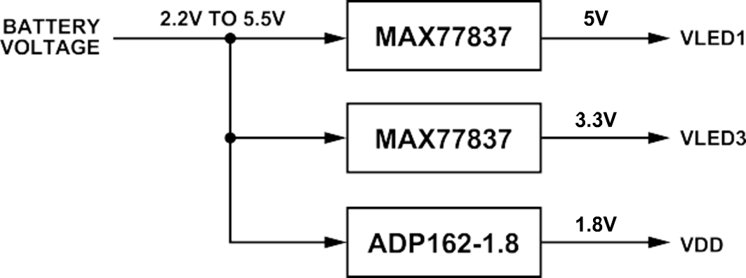
The integrated IR and Blue LEDs of the ADPD188BI require 3.3 V and 5 V power rails, respectively. The external supply voltage is fed into two MAX77837 buck-boost converters, where the output voltage of a MAX77837 is determined by an external resistor selection. Setting the resistor to 402 kΩ and 324 kΩ results in the desired output voltage of 3.3 V and 5 V, respectively.
The core digital voltage required to power the ADPD188BI, MAX31875, and MAX32660 is derived from the ADP162. This CMOS linear regulator has an input voltage range of 2.2 V to 5.5 V and a maximum output current of 150 mA. The output voltage of the ADP162 is fixed to 1.8 V and only requires input and output capacitors for operation, greatly simplifying the circuit design.
While smoke detector regulations vary, there is a common trend to require battery powered smoke detectors to have a sealed, non-removable, and non-rechargeable 10-year battery. As such, one of the biggest challenges in designing smoke detection systems is to maintain the sensor performance while minimizing the amount of supply current drawn to extend battery life.
Figure 11 shows the entire CN0583 SOM power consumption during measurement and processing as well as when in sleep mode.
The CN0583 SOM has a quiescent current of 8.22 μA with no LED pulse on. The ADP162 regulator and MAX77837 buck-boost converters used to generate the system supply voltages have ultralow quiescent currents of only 560 nA and 430 nA, respectively. The MAX32660 microcontroller has a quiescent current of 2 μA to retain data, and the ADP162 1.8 V LDO draws ~3 μA; leaving approximately 3.2 μA for both boost converters and temperature sensor.
In addition, the active measurement and processing time of the ADPD188BI and MAX32660 have been optimized. During the active "ON" times, the board has an average power of 6.5 μA with both the IR and Blue LEDs firing the current peaks to ~6.8 mA for 5 ms at 3.6 V. This pulse happens once every 6 seconds, and this 6.5 μA adds to the 8.22 μA quiescent current; bringing the total system current to 14.72 μA. Using only a single LED further reduces the total system current to 9.7 μA for the IR LED or 11.8 μA for Blue LED.

Carrier Board
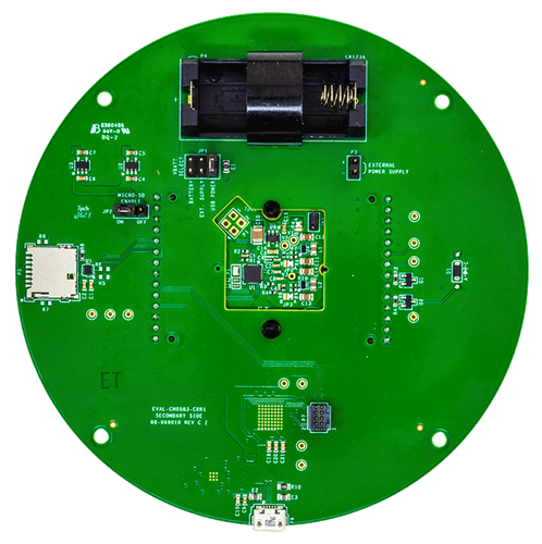
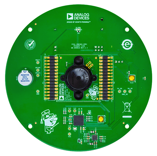
An easy-to-use carrier board enables evaluation, development, and prototyping of the CN0583 SOM without soldering or custom board development. Electrical connections to the carrier board are made via spring-loaded connectors aligned with the SOM castellation, effectively clipping the SOM in place once inserted between them.
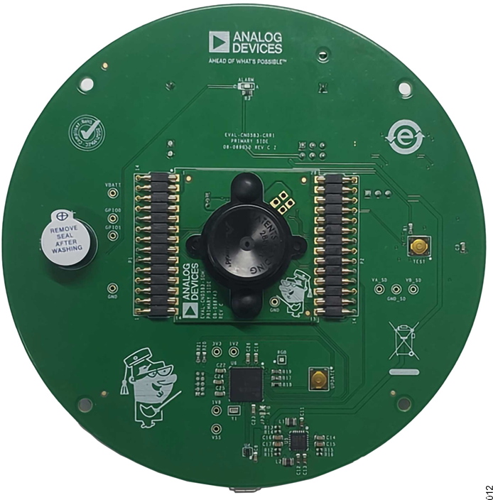
The carrier board can be used to easily program, configure, and capture data from the CN0583 SOM via the DAPLink. An on-board LED and buzzer circuit serves as simple alarm indicators, triggered by the CN0583 SOM hardware and embedded algorithm when the smoke events have been identified. A slot for a micro-SD card can be used to save sensor data read from the SOM during operation. The carrier board also provides multiple options for the SOM power source such as a CR123A battery holder and a micro-USB connector.
Common Variations
If board space is incredibly constrained, an alternative power solution to the MAX77837 and ADP162 is to use a multiple-output power management IC (PMIC) such as the MAX77643. This PMIC integrates a triple-output single-inductor multiple-output (SIMO) buck-boost converter and a low dropout regulator, allowing it to generate all of the ADPD188BI supply voltages by itself. In addition, the buck-boost converter of the MAX77643 only requires a single inductor for operation, resulting in an even smaller footprint.
For applications that require a lower profile solution, it is possible to operate the ADPD188BI without its smoke chamber thanks to its excellent ambient light rejection. This will however, require further data research and custom algorithm development.
Analog Devices also offers the CN0537 smoke detector solution, providing a similar functionality and performance, but in an Arduino compatible form factor. This allows for test and development using alternative processors, but is not as optimized for power considerations.
Carbon monoxide can be added to the system by migrating the microcontroller from the MAX32660 to the MAX32662. The MAX32662 includes an integrated 4-channel 12-bit 1 MSPS ADC. A UL-registered electrochemical CO sensor such as the Figaro TGS5141 or similar can be attached to the ADC by adding a single op-amp set up as a transimpedance amplifier (TIA) with an Rf of 1 MΩ and a Cf of 1 µF. The LTC2063 op-amp is recommended to be used as TIA for this setup. This part has an input voltage offset of less than 30 µV, which is required for the CO sensor. Also, the part's voltage rail is as low as 1.8 V to match the microcontroller; with power-down input to enable power-down by the microcontroller when not in use. Figure 13 shows the adjusted signal chain setup to accommodate carbon monoxide sensing.

Circuit Evaluation & Test
The following section outlines the general setup for evaluation the CN0583. For complete setup and other detailed instructions, please refer to the CN0583 User Guide.
EQUIPMENT NEEDED
- EVAL-CN0583-SOM
- EVAL-CN0583-CRR1 carrier board
- Micro USB to USB Type A cable
- PC with a USB port
- Serial terminal application
- CN0583 demo application .HEX file
Setup and Test
For system evaluation, the CN0583 includes application software that allows the user to communicate with the SOM using the carrier board by following the steps below:
- Download the latest version of the CN0583 application software (*.hex) file from the CN0583 User Guide.
- Insert the EVAL-CN0583-SOM module into the cutout of the EVAL-CN0583-CRR1.
- Ensure that the module is in correct orientation such that Pin 1 is closest to the buzzer and Pin 28 is on the side with the test button.
- The castellated pins on the EVAL-CN0583-SOM should be lined up with the pogo pins of the EVAL-CN0583-CRR1.
- Gently press the EVAL-CN0583-SOM down and to the right so that you “press” the pogo pins inward on the right-hand side.
- With the castellated pins of the SOM pressed into the pogo pins, slowly move the left-hand side of the EVAL-CN0583-SOM downward until it contacts the other set of pogo pins and is flush with the EVAL-CN0583-CRR1.
- Connect a micro-USB cable to the P6 connector of the carrier board and connect the other end of the USB cable to a computer. The board should appear as an external DAPLink.

Figure 14. CN0583 Test Setup - Run the serial terminal program on the computer:
- Open a serial connection to the CN0583's COM port.
- Set the baud rate to 115200 and stop bits to 2, as shown in Figure 15.

Figure 15. Serial Terminal Connection Configurations - Type h into the serial terminal to display the list of available commands.
- Type, s, the command to start the data stream. The software begins capturing the blue and infrared responses and displays them on the serial terminal in PTR values.
- Type, i, the command, to stop the data stream.

Figure 16. CN0583 Smoke Detector Data Measurement
