MAX5974A
RECOMMENDED FOR NEW DESIGNSActive-Clamped, Spread-Spectrum, Current-Mode PWM Controllers
Active-Clamped, Spread-Spectrum, Current-Mode PWM Controllers with Adjustable Frequency from 100kHz to 600kHz
- Part Models
- 2
- 1ku List Price
- Starting From $1.13
Overview
- Peak Current-Mode Control, Active-Clamped Forward PWM Controller
- Regulation Without Optocoupler (MAX5974A/MAX5974B)
- Internal 1% Error Amplifier
- 100kHz to 600kHz Programmable ±8% Switching Frequency, Synchronization Up to 1.2MHz
- Programmable Frequency Dithering for Low-EMI, Spread-Spectrum Operation
- Programmable Dead Time, PWM Soft-Start, Current Slope Compensation
- Programmable Feed-Forward Maximum Duty-Cycle Clamp, 80% Maximum Limit
- Frequency Foldback for High-Efficiency Light-Load Operation
- Internal Bootstrap UVLO with Large Hysteresis
- 100µA (typ) Startup Supply Current
- Fast Cycle-by-Cycle Peak Current-Limit, 35ns Typical Propagation Delay
- 115ns Current-Sense Internal Leading-Edge Blanking
- Output Short-Circuit Protection with Hiccup Mode
- Reverse Current Limit to Prevent Transformer Saturation Due to Reverse Current
- Internal 18V Zener Clamp on Supply Input
- 3mm x 3mm, Lead-Free, 16-Pin TQFN-EP
The MAX5974_ provide control for wide-input-voltage, active-clamped, current-mode PWM, forward converters in Power-over-Ethernet (PoE) powered device (PD) applications. The MAX5974A/MAX5974C are well-suited for universal or telecom input range, while the MAX5974B/MAX5974D also accommodate low input voltage down to 10.5V.
The devices include several features to enhance supply efficiency. The AUX driver recycles magnetizing current instead of wasting it in a dissipative clamp circuit. Programmable dead time between the AUX and main driver allows for zero-voltage switching (ZVS). Under light-load conditions, the devices reduce the switching frequency (frequency foldback) to reduce switching losses.
The MAX5974A/MAX5974B feature unique circuitry to achieve output regulation without using an optocoupler, while the MAX5974C/MAX5974D utilize the traditional optocoupler feedback method. An internal error amplifier with a 1% reference is very useful in nonisolated design, eliminating the need for an external shunt regulator.
The devices feature a unique feed-forward maximum duty-cycle clamp that makes the maximum clamp voltage during transient conditions independent of the line voltage, allowing the use of a power MOSFET with lower breakdown voltage. The programmable frequency dithering feature provides low-EMI, spread-spectrum operation.
The MAX5974_ are available in 16-pin TQFN-EP packages and are rated for operation over the -40°C to +85°C and -40°C to +125°C temperature ranges.
Applications
- Active-Clamped Forward DC-DC Converters
- High-Power PD (Beyond the 802.3af/at Standard)
- IP Phones
- PoE IEEE® 802.3af/at Powered Devices
- Security Cameras
- Wireless Access Nodes
Documentation
Data Sheet 1
Technical Articles 4
Rarely Asked Question 1
ADI has always placed the highest emphasis on delivering products that meet the maximum levels of quality and reliability. We achieve this by incorporating quality and reliability checks in every scope of product and process design, and in the manufacturing process as well. "Zero defects" for shipped products is always our goal. View our quality and reliability program and certifications for more information.
| Part Model | Pin/Package Drawing | Documentation | CAD Symbols, Footprints, and 3D Models |
|---|---|---|---|
| MAX5974AETE+ | Thin Quad Flatpack, No Leads | ||
| MAX5974AETE+T | Thin Quad Flatpack, No Leads |
| Part Models | Product Lifecycle | PCN |
|---|---|---|
|
Apr 20, 2026 - 2571D PIN/ERRATA |
||
| MAX5974AETE+ | PRODUCTION | |
| MAX5974AETE+T | PRODUCTION | |
|
Aug 2, 2025 - 2505 PIN/ERRATA |
||
| MAX5974AETE+ | PRODUCTION | |
|
Sep 18, 2020 - 2054 ASSEMBLY |
||
| MAX5974AETE+ | PRODUCTION | |
| MAX5974AETE+T | PRODUCTION | |
|
Jun 20, 2016 - 1612 ASSEMBLY |
||
| MAX5974AETE+ | PRODUCTION | |
| MAX5974AETE+T | PRODUCTION | |
|
Jan 7, 2014 - 1363 ASSEMBLY |
||
| MAX5974AETE+ | PRODUCTION | |
| MAX5974AETE+T | PRODUCTION | |
This is the most up-to-date revision of the Data Sheet.
Software Resources
Can't find the software or driver you need?
Request a Driver/SoftwareHardware Ecosystem
| Parts | Product Life Cycle | Description |
|---|---|---|
| Switching Regulators & Controllers 6 | ||
| MAX5003 | NOT RECOMMENDED FOR NEW DESIGNS | High-Voltage PWM Power-Supply Controller |
| MAX5015 | NOT RECOMMENDED FOR NEW DESIGNS | Current-Mode PWM Controllers with Integrated Startup Circuit for Isolated Power Supplies |
| MAX5094 | PRODUCTION | High-Performance, Single-Ended, Current-Mode PWM Controllers |
| MAX5070 | PRODUCTION | High-Performance, Single-Ended, Current-Mode PWM Controllers |
| MAX5022 | PRODUCTION | Current-Mode PWM Controllers for Isolated Power Supplies |
| MAX5021 | PRODUCTION | Current-Mode PWM Controllers for Isolated Power Supplies |
Evaluation Kits
Evaluation Kit for the MAX5974A
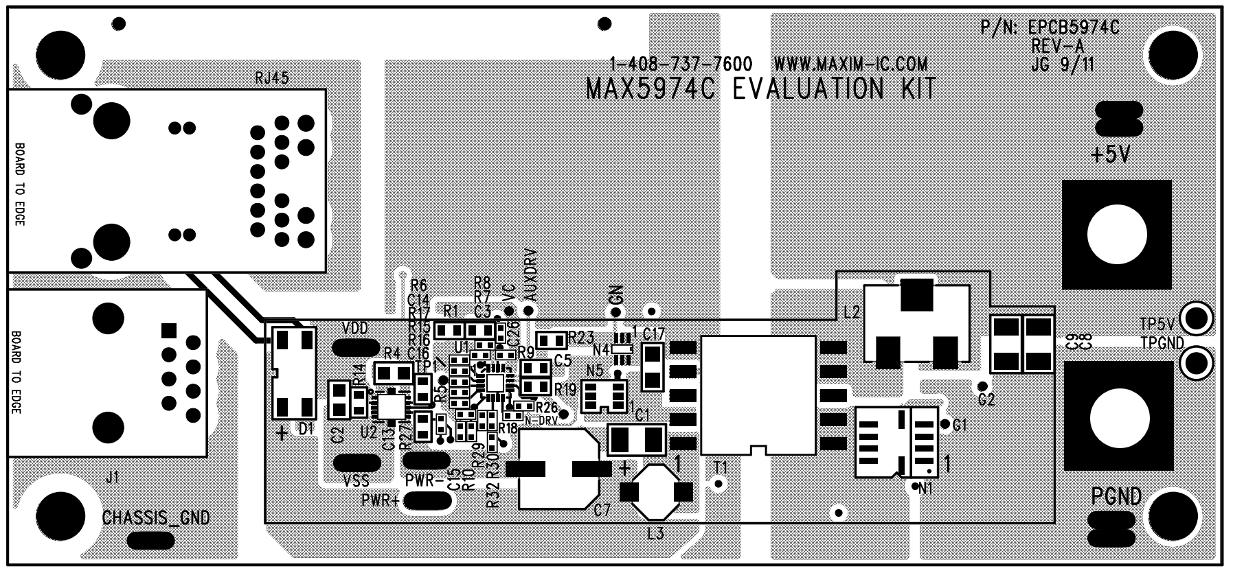

Evaluation Kit for the MAX5974C
Resources
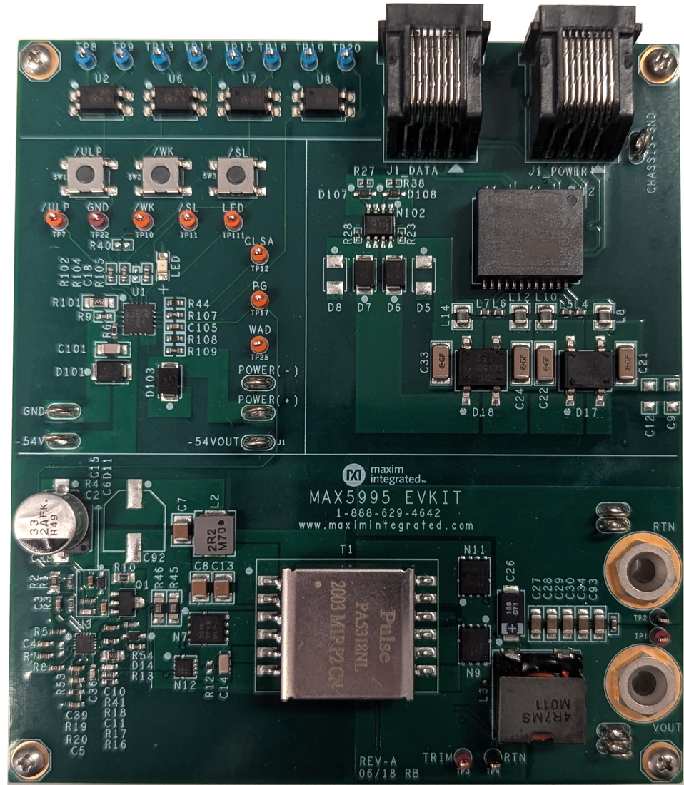

Evaluation Kit for the MAX5995A, MAX5995B, MAX5995C, MAX5974D
Resources
Reference Designs

65W POE Solution Using the MAX5974A and MAX5995B
Part Used
Design & Integration Tools


3.3V and 5V PoE Powered Device
Part Used
Design & Integration Tools
Latest Discussions
No discussions on MAX5974A yet. Have something to say?
Start a Discussion on EngineerZone®