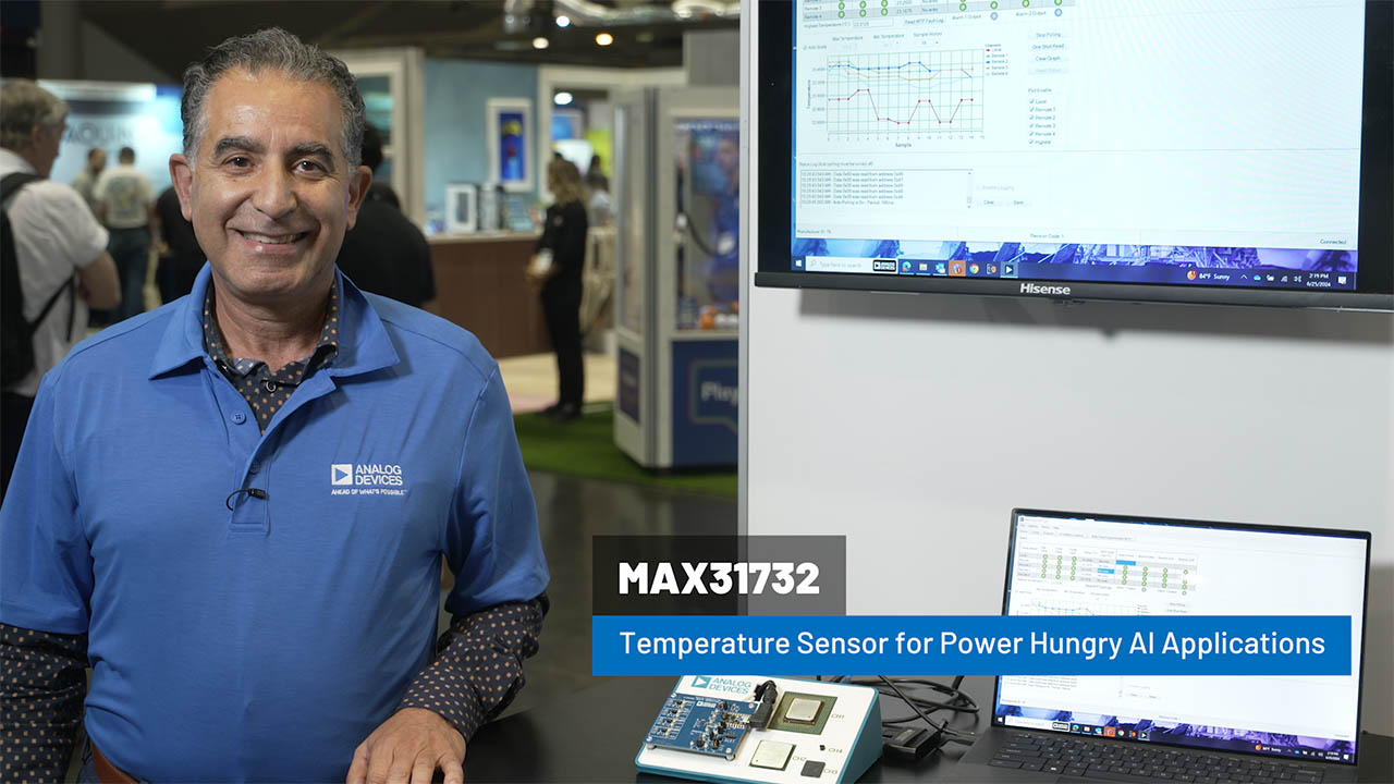
MAX31732
RECOMMENDED FOR NEW DESIGNSFour-Channel Remote Temperature Sensor
- Part Models
- 2
- 1ku List Price
- Starting From $2.96
Overview
- One Local and Four Remote Temperature-Sensing Channels
- ±1°C Remote Temperature-Measurement Accuracy (-40°C to +125°C)
- -64°C to +150°C Remote Temperature- Measurement Range
- Up to 300Ω Resistance Cancellation for Remote Channels
- Compensation for Low Beta Transistors
- Two Programmable Alarm Temperature Thresholds
- 12 Bit, 0.0625°C Resolution
- Eight Selectable Target Addresses
- Flexible I2C/SMBus Interfaces to a Variety of Microcontrollers
- Ideality Factor of up to 1.311
- NVM Facilitates Configuration and Fault Logging
The MAX31732 is a multi-channel temperature sensor that monitors its own temperature and the temperatures of up to four external diode-connected transistors. A resistance cancellation feature compensates for up to 300Ω of series resistance between the external thermal diode and the MAX31732, while beta compensation corrects for temperature-measurement errors due to low-beta sensing transistors. The sensor also allows ideality factors between 0.9844 and 1.311.
The MAX31732 offers two open-drain, active-low alarm outputs, ALARM1 and ALARM2. When the measured temperature of a channel crosses the respective primary overtemperature/undertemperature threshold levels, ALARM1 asserts low, and a status bit is set in the corresponding thermal status registers. When the measured temperature of a channel crosses the secondary overtemperature/undertemperature threshold levels, ALARM2 asserts low and a status bit is set in the corresponding thermal status registers. The highest temperature register allows the controller to obtain the temperature of the hottest channel.
A 512-bit nonvolatile memory (NVM) allows the MAX31732 to program the configuration registers during power-up without software/firmware intervention. The NVM also captures the fault temperature for each remote and local channel for further analysis at a later time.
The 2-wire serial interface accepts SMBus protocols (write byte, read byte, send byte, and receive byte) for reading the temperature data and programming the temperature thresholds. Any one of the eight available target addresses can be selected using the address selection input (ADD), which can be connected to ground or connected to a grounded resistor.
The is specified over the -40°C to +125°C operating temperature range and with a 3.0V to 3.6V input supply range. MAX31732 is available in a 24-pin, 4mm x 4mm TQFN package.
Applications
- Temperature Measurement of On-Chip CPU, ASIC, SOC, or FPGA diodes or remote discrete diodes
- Industrial-Thermal Management
Documentation
Video 1
Analog Dialogue 1
ADI has always placed the highest emphasis on delivering products that meet the maximum levels of quality and reliability. We achieve this by incorporating quality and reliability checks in every scope of product and process design, and in the manufacturing process as well. "Zero defects" for shipped products is always our goal. View our quality and reliability program and certifications for more information.
| Part Model | Pin/Package Drawing | Documentation | CAD Symbols, Footprints, and 3D Models |
|---|---|---|---|
| MAX31732ATG+ | 24-TQFN-4X4X0.75 | ||
| MAX31732ATG+T | 24-TQFN-4X4X0.75 |
This is the most up-to-date revision of the Data Sheet.


