

LTC3554
LTC3554-1
LTC3554-2
LTC3554-3
RECOMMENDED FOR NEW DESIGNS
Micropower USB Power Manager with Li-Ion Charger and Two Step-Down Regulators
- Part Models
- 8
- 1ku List Price
- Starting From $3.60
Overview
- 10μA Standby Mode Quiescent Current (All Outputs On)
- Seamless Transition Between Input Power Sources: Li-Ion/Polymer Battery and USB
- 240mΩ Internal Ideal Diode
- Dual High Efficiency Step-Down Switching Regulators (200mA IOUT) with Adjustable Output Voltages
- Pushbutton On/Off Control with System Reset
- Reset Time: 5 sec (LTC3554/LTC3554-1), 14 sec (LTC3554-2/LTC3554-3)
- Full Featured Li-Ion/Polymer Battery Charger
- Programmable Charge Current with Thermal Limiting
- Instant-On Operation with Discharged Battery
- Battery Float Voltage: 4.2V (LTC3554/LTC3554-2/LTC3554-3), 4.1V (LTC3554-1)
- 3mm × 3mm × 0.75mm 20-Lead QFN Package
The LTC3554 family are micropower, highly integrated power management and battery charger ICs for single-cell Li-Ion/Polymer battery applications. They include a PowerPath™ manager with automatic load prioritization, a battery charger, an ideal diode and numerous internal protection features. Designed specifically for USB applications, the LTC3554 power managers automatically limit input current to a maximum of either 100mA or 500mA. Battery charge current is automatically reduced such that the sum of the load current and the charge current does not exceed the selected input current limit.
The LTC3554 also includes two synchronous step-down switching regulators as well as a pushbutton controller. With all supplies enabled in standby mode, the quiescent current drawn from the battery is only 10μA. The LTC3554 family are available in a 3mm × 3mm × 0.75mm 20-lead QFN package.
Applications
- USB-Based Handheld Products
- Portable Li-Ion/Polymer Based Electronic Devices
- Fitness Computers
- Low Power Medical Devices
Documentation
Data Sheet 1
User Guide 1
ADI has always placed the highest emphasis on delivering products that meet the maximum levels of quality and reliability. We achieve this by incorporating quality and reliability checks in every scope of product and process design, and in the manufacturing process as well. "Zero defects" for shipped products is always our goal. View our quality and reliability program and certifications for more information.
| Part Model | Pin/Package Drawing | Documentation | CAD Symbols, Footprints, and 3D Models |
|---|---|---|---|
| LTC3554EUD#PBF | 20-Lead QFN (3mm x 3mm x 0.75mm w/ EP) | ||
| LTC3554EUD#TRPBF | 20-Lead QFN (3mm x 3mm x 0.75mm w/ EP) | ||
| LTC3554EUD-1#PBF | 20-Lead QFN (3mm x 3mm x 0.75mm w/ EP) | ||
| LTC3554EUD-1#TRPBF | 20-Lead QFN (3mm x 3mm x 0.75mm w/ EP) | ||
| LTC3554EUD-2#PBF | 20-Lead QFN (3mm x 3mm x 0.75mm w/ EP) | ||
| LTC3554EUD-2#TRPBF | 20-Lead QFN (3mm x 3mm x 0.75mm w/ EP) | ||
| LTC3554EUD-3#PBF | 20-Lead QFN (3mm x 3mm x 0.75mm w/ EP) | ||
| LTC3554EUD-3#TRPBF | 20-Lead QFN (3mm x 3mm x 0.75mm w/ EP) |
This is the most up-to-date revision of the Data Sheet.
Software Resources
Can't find the software or driver you need?
Request a Driver/SoftwareHardware Ecosystem
| Parts | Product Life Cycle | Description |
|---|---|---|
| Battery Monitors & Fuel Gauges 1 | ||
| LTC2942 | Obsolete | Battery Gas Gauge with Temperature, Voltage Measurement |
| Circuit Monitors 1 | ||
| LTC2960 | RECOMMENDED FOR NEW DESIGNS | 36V Nano-Current Two-Input Voltage Monitor |
| Hot Swap Controllers 1 | ||
|
LTC4362-1 LTC4362-2 |
1.2A Overvoltage/Overcurrent Protector | |
| Ideal Diodes and PowerPath Controllers 1 | ||
| LTC2955 | RECOMMENDED FOR NEW DESIGNS | Pushbutton On/Off Controller with Automatic Turn-On |
Evaluation Kits
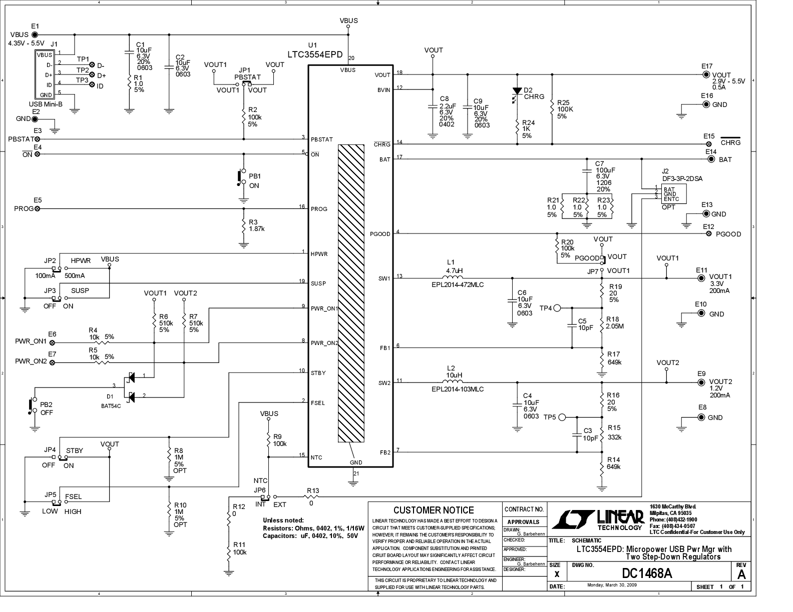
LTC3554EPD Demo Board | Micropower USB Power Manager with Li-Ion Charger and Dual 200mA Buck Regulator