LTC1702A
Info: : PRODUCTION
searchIcon
cartIcon

LTC1702A

Dual 550kHz Synchronous 2-Phase Switching Regulator Controller

Show More showmore-icon

Info: : PRODUCTION tooltip
Part Details
Part Models 4
1ku List Price Starting From $6.28
Features
  • Pin Compatible with the LTC1702 with Improved Current Limit Control
  • Two Sides Run Out-of-Phase to Minimize CIN
  • No External Current Sense Resistors
  • Excellent Output Regulation: 1% Total Output Accuracy
  • Two Independent Controllers in One Package
  • All N-Channel External MOSFET Architecture
  • 550kHz Switching Frequency Minimizes External Component Size
  • 1A to 25A Output Current per Channel
  • High Efficiency over Wide Load Current Range
  • Less Than 100µA Shutdown Current
  • Small 24-Pin Narrow SSOP Package
Additional Details
show more Icon

The LTC1702A is a dual switching regulator controller optimized for high efficiency with low input voltages. It includes two complete, on-chip,independent switching regulator controllers each designed to drive a pair of external N-channel MOSFETs in a voltage mode feedback,synchronous buck configuration. The LTC1702A uses a constant-frequency, true PWM design switching at 550kHz, minimizing external component size and cost and maximizing load transient performance. The synchronous buck architecture automatically shifts to discontinuous and then to Burst Mode® operation as the output load decreases, ensuring maximum efficiency over a wide range of load currents.

The LTC1702A features an onboard reference trimmed to 0.5% and can provide better than 1% regulation at the converter outputs. Open-drain logic outputs indicate whether either output has risen to within 5% of the final output voltage and an optional latching FAULT mode protects the load if the output rises 15% above the intended voltage. Each channel can be enabled independently; with both channels disabled, the LTC1702A shuts down and supply current drops below 100µA.

Applications

  • Microprocessor, DSP Core and I/O Supplies
  • Multiple Logic Supply Generator
  • Distributed Power Applications
  • High Efficiency Power Conversion
Part Models 4
1ku List Price Starting From $6.28

close icon
Documentation

Documentation

Part Model Pin/Package Drawing Documentation CAD Symbols, Footprints, and 3D Models
LTC1702ACGN#PBF
  • HTML
  • HTML
LTC1702ACGN#TRPBF
  • HTML
  • HTML
LTC1702AIGN#PBF
  • HTML
  • HTML
LTC1702AIGN#TRPBF
  • HTML
  • HTML

Filter by Model

reset

Reset Filters

Part Models

Product Lifecycle

PCN

Aug 10, 2022

- 22_0177

Laser Top Mark Conversion for QSOP20_24_28 Assembled in ADPG [PNG] and UTL

LTC1702ACGN#PBF

PRODUCTION

LTC1702ACGN#TRPBF

PRODUCTION

LTC1702AIGN#PBF

PRODUCTION

LTC1702AIGN#TRPBF

PRODUCTION

Filter by Model

reset

Reset Filters

Part Models

Product Lifecycle

PCN

Aug 10, 2022

- 22_0177

arrow down

Laser Top Mark Conversion for QSOP20_24_28 Assembled in ADPG [PNG] and UTL

LTC1702ACGN#PBF

PRODUCTION

LTC1702ACGN#TRPBF

PRODUCTION

LTC1702AIGN#PBF

PRODUCTION

LTC1702AIGN#TRPBF

PRODUCTION

Software & Part Ecosystem

Software & Part Ecosystem

Evaluation Kit

Evaluation Kits 2

reference details image

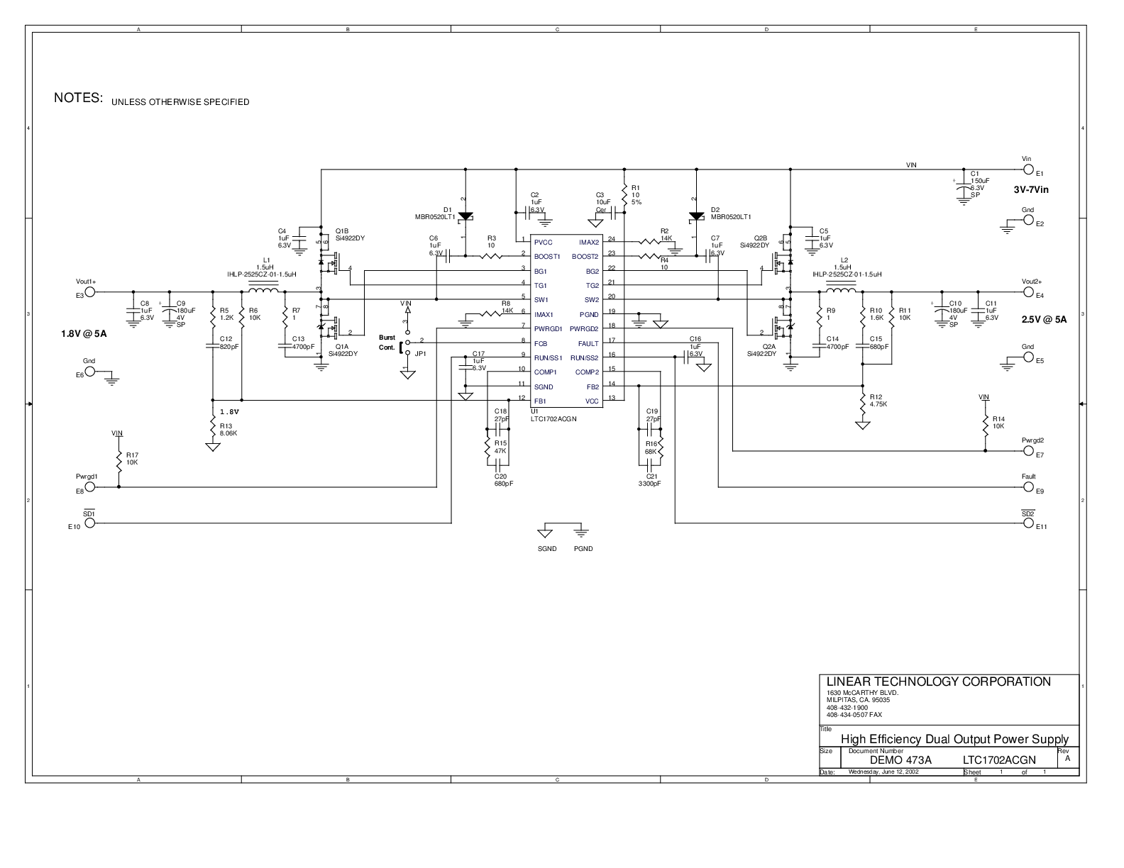
DC473A

LTC1702ACGN | High Efficiency Dual Output Power Supply, 3V~7VIN, 1.8VOUT @ 5A and 2.5VOUT @ 5A

reference details image

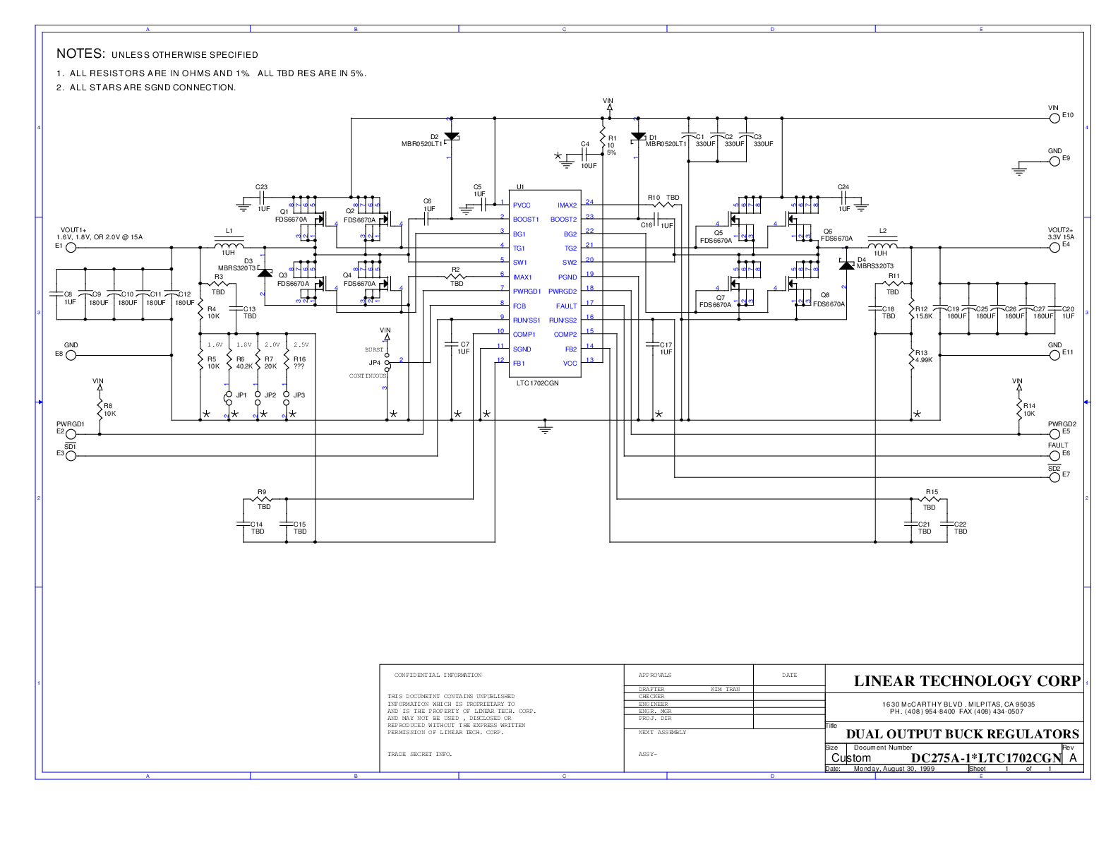
DC275A

LTC1702ACGN | Dual Output Buck Regulators, VIN = 5.0V, Fswitch = 550kHz, VOUT1 = Jumper Selectable @ 15A, VOUT2 = 3.3V @ 15A

zoom

DC275A

LTC1702ACGN | Dual Output Buck Regulators, VIN = 5.0V, Fswitch = 550kHz, VOUT1 = Jumper Selectable @ 15A, VOUT2 = 3.3V @ 15A

LTC1702ACGN | Dual Output Buck Regulators, VIN = 5.0V, Fswitch = 550kHz, VOUT1 = Jumper Selectable @ 15A, VOUT2 = 3.3V @ 15A

Product Detail

DC275A: Demo Board for the LTC1702A Dual 550kHz Synchronous 2-Phase Switching Regulator Controller.

Tools & Simulations

Tools & Simulations 1

LTspice® is a powerful, fast and free simulation software, schematic capture and waveform viewer with enhancements and models for improving the simulation of analog circuits.

To launch ready-to-run LTspice demonstration circuits for this part:

Step 1: Download and install LTspice on your computer.

Step 2: Click on the link in the section below to download a demonstration circuit.

Step 3: If LTspice does not automatically open after clicking the link below, you can instead run the simulation by right clicking on the link and selecting “Save Target As.” After saving the file to your computer, start LTspice and open the demonstration circuit by selecting ‘Open’ from the ‘File’ menu.

Recently Viewed