

μModule Power Technology
μModule® power regulator technology simplifies implementation, verification, and manufacturing of complex power circuits by integrating the power function into one compact package. This system-in-package (SiP) approach streamlines the design process and reduces component count by minimizing the need to add external components.
Value and Benefits
- Complete SiP Power: With controllers, transistors, capacitors, compensation, and inductors in a compact BGA/LGA package
- Versatile Functions: Buck, buck-boost, battery charger, isolated converter, and LED driver
- Compact Integration: Simplifies design, saves space, and minimizes external components
- Wide Market Use: Industrial, aerospace, communications, instrumentation
Highly integrated solutions that reduce design time and PCB space concerns
Easy Implementation with Minimal External Components
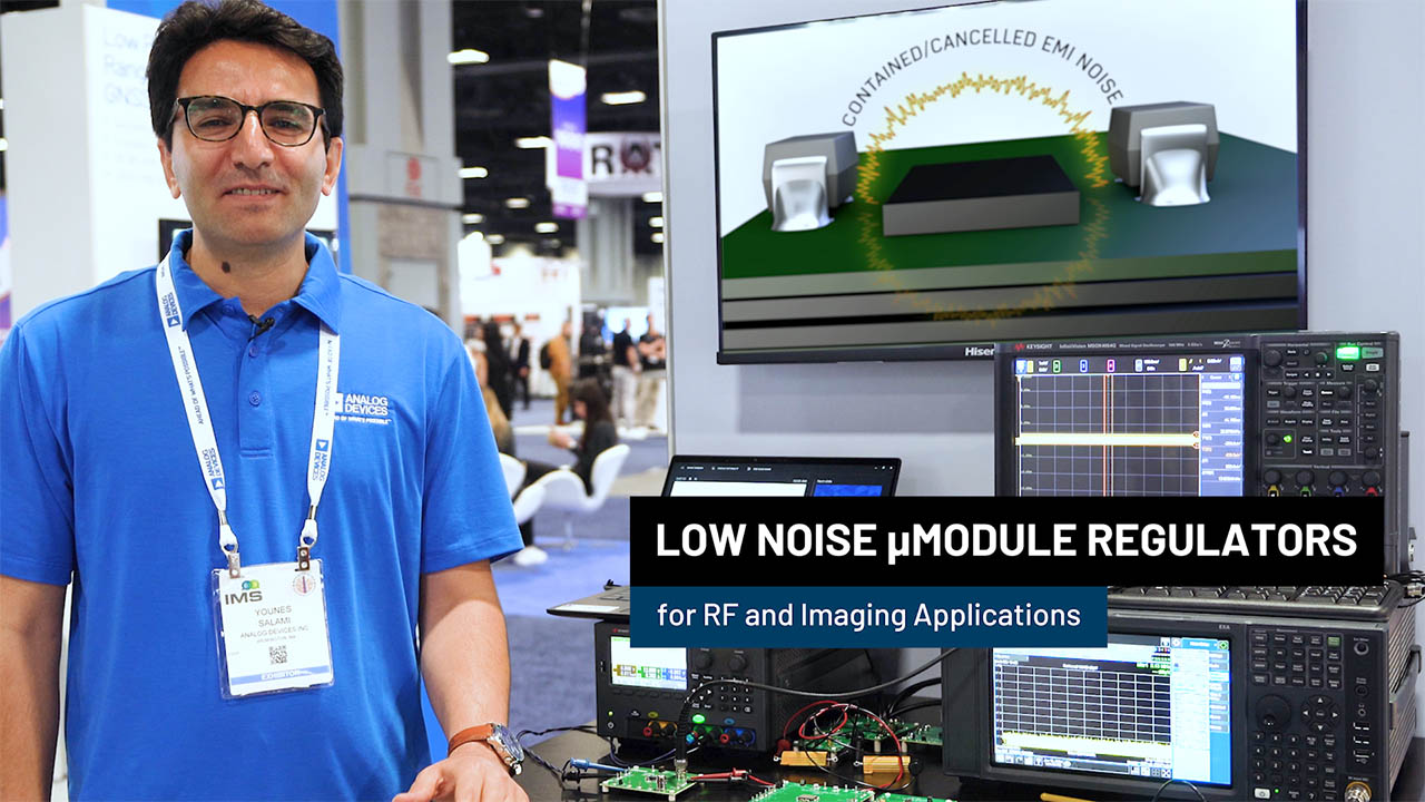
Complete system-in-package (SiP) power management integrates the DC-to-DC controllers, power transistors, input and output capacitors, compensation components, and inductors into one device to deliver a reliable, high-efficiency, and low EMI noise power solution.
Ultrathin Package for Space Constrained Applications
The package height of the ultrathin µModule Regulator product family is 1.82mm or 1.91mm (LGA). This thin package allows placement on the backside of the PCB or under a common heat sink with digital devices such as FPGAs, GPUs, ASICs, and processors. These parts are also offered in a BGA package (0.6mm taller than LGA).
Standard Packaging Simplifies Design Layout
µModule power products are provided in BGA and LGA packages. The pad assignment of the package is uniform for easy PCB design. Both RoHS compliant and SnPb terminal finishes are available in the BGA package.
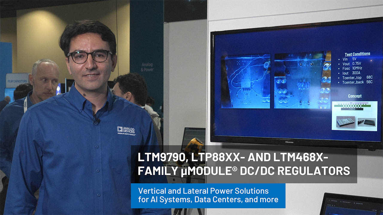
Vertical and Lateral Power Solutions for AI Systems, Data Centers

Application Interactive µModule Infographics Tool
Sort options based on your application. Use this interactive infographic to easily identify the right µModule for your design.

Function Interactive µModule Infographics Tool
Sort options based on component function. Use this interactive infographic to easily identify the right µModule for your design.

Package Interactive µModule Infographics Tool
Sort options based on component package. Use this interactive infographic to easily identify the right µModule for your design.
 Manufacturing and Assembly Resources
Assembly Considerations for µModule® BGA and LGA PackagesDiscover a complete guide to:
|
µModule LGA and BGA Packaging Care and Assembly InstructionsA brief reference on handling moisture sensitivity, reflow and assembly for the LGA and BGA packages
|
µModule Regulator Printed Circuit Board Design GuidelinesThese guidelines provide insight into the process of designing the PCB layout for µModules
|
Package & Board Level ReliabilityAnalog Devices is committed to continuously improving its world-class product reliability levels and has some of the highest reliability standards in the industry
|
µModule LGA PackagesOutline drawings for LGA packages
|
µModule BGA PackagesOutline drawings and information for BGA packages
|
µModule LGA Shipping TrayShipping Tray drawings and information for LGA packages
|
µModule BGA Shipping TrayShipping Tray drawings and information for BGA packages
|
Solution Resources
Hardware Products


Developer Tools and Resources

Simulation Models


Files and Downloads
Application Note

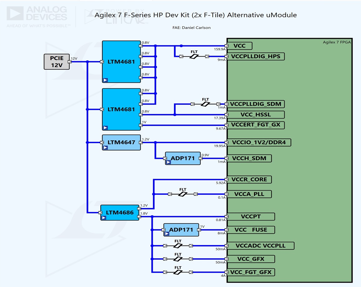
AN119A - Powering Complex FPGA-Based Systems Using Highly Integrated DC/DC uModule Regulator Systems
![]()
499.00K
AN110 - LTM4601 DC/DC uModule Thermal Performance
![]()
188.00K
AN103 - LTM4600 DC/DC uModule Thermal Performance
![]()
183.00K
AN119B - Powering Complex FPGA-Based Systems Using Highly Integrated DC/DC uModule Regulator Systems
![]()
283.00K
Design Note
DN1021 - How to Produce Negative Output Voltages from Positive Inputs Using a uModule Step-Down Regulator
![]()
117.00K
DN385 - 10A High Performance Point-of-Load DC/DC uModule
![]()
145.00K
DN438 - uModule Buck-Boost Regulators Offer a Simple and Efficient Solution for Wide Input and Output Voltage Range Applications
![]()
96.00K
DN430 - 8A Low Voltage, Low Profile DC/DC Module Regulator in 9mm x 15mm Package Weighs Only 1g
![]()
90.00K
DN411 - Simple and Compact 4-Output Point-of-Load DC/DC uModule System
![]()
688.00K
Design Tool

PPTX
Package Interactive µModule Infographics Tool
![]()
19.95 M
PPTX
Function Interactive µModule Infographics Tool
![]()
8.45 M
PPTX
Application Interactive µModule Infographics Tool
![]()
31.34 M
Product Information
Assembly Considerations for µModule® BGA and LGA Packages
![]()
3.06 M
Quality Documentation
uModule LGA and BGA Packaging Care and Assembly Instructions
![]()
466.00K
Solutions Bulletin & Brochure
Digital Power System Management Brochure
![]()
undefined
Balanced Power Solutions Brochure
![]()
461.79 K
µModule Power Products
![]()
9.87 M
{{modalTitle}}
{{modalDescription}}
{{dropdownTitle}}
- {{defaultSelectedText}} {{#each projectNames}}
- {{name}} {{/each}} {{#if newProjectText}}
-
 {{newProjectText}}
{{/if}}
{{newProjectText}}
{{/if}}
{{newProjectTitle}}
{{projectNameErrorText}}