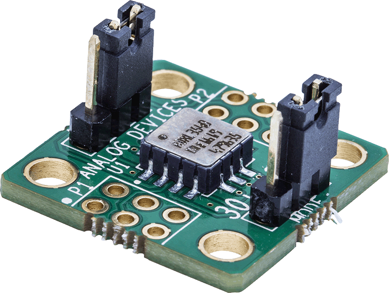
ADXL355
Low-Noise, Low-Drift, Low-Power, 3-Axis MEMS Accelerometers
Show More
Not the part you were looking for?
Ask a Question
Submit your question below and we will return the best answer from ADI’s knowledge database:
Other places you can find help
Support
Analog Devices Support Portal is a one-stop shop to answer all your ADI questions.
Visit the ADI Support PageFeatures
- Hermetic package offers excellent long-term stability
- 0 g offset vs. temperature (all axes): 0.15 mg/°C maximum
- Ultralow noise density (all axes): 22.5µg/√Hz
- Low power, VSUPPLY (LDO regulator enabled)
- ADXL354 in measurement mode: 150 μA
- ADXL355 in measurement mode: 200 μA
- ADXL354/ADXL355 in standby mode: 21 μA
- ADXL354 has user adjustable analog output bandwidth
- Electromechanical self test
- Integrated temperature sensor
- ADXL355 digital output features
- Digital SPI and I2C interfaces supported
- 20-bit ADC
- Data interpolation routine for synchronous sampling
- Programmable high- and low-pass digital filters
- Voltage range options
- VSUPPLY with internal regulators: 2.25 V to 3.6 V
- V1P8ANA, V1P8DIG with internal LDO regulator bypassed: 1.8 V typical ± 10%
- Operating temperature range: −40°C to +125°C
- 14-terminal, 6 mm × 5.6 mm × 2.2 mm, LCC package
The analog output ADXL354 and the digital output ADXL355 are low noise density, low 0 g offset drift, low power, 3-axis accelerometers with selectable measurement ranges. The ADXL354B supports the ±2 g and ±4 g ranges, the ADXL354C supports the ±2 g and ±8 g ranges, and the ADXL355 supports the ±2 g, ±4 g, and ±8 g ranges. The ADXL354/ADXL355 offer industry leading noise, minimal offset drift over temperature, and long-term stability enabling precision applications with minimal calibration.
Highly integrated in a compact form factor, the low power ADXL355 is ideal in an Internet of Things (IoT) sensor node and other wireless product designs.
The ADXL355 multifunction pin names may be referenced by their relevant function only for either the serial peripheral interface (SPI) or I2C interface.
Applications
- Inertial measurement units (IMUs)/altitude and heading reference systems (AHRS)
- Platform stabilization systems
- Structural health monitoring
- Seismic imaging
- Tilt sensing
- Robotics
- Condition Monitoring
Ask a Question
Submit your question below and we will return the best answer from ADI’s knowledge database:
Other places you can find help
Support
Analog Devices Support Portal is a one-stop shop to answer all your ADI questions.
Visit the ADI Support Page{{modalTitle}}
{{modalDescription}}
{{dropdownTitle}}
- {{defaultSelectedText}} {{#each projectNames}}
- {{name}} {{/each}} {{#if newProjectText}}
- {{newProjectText}} {{/if}}
{{newProjectTitle}}
{{projectNameErrorText}}
ADXL355
Documentation
Filters
1 Applied
Data Sheet
2
User Guide
3
WIKI
WIKI
Technical Articles
27
HTML
HTML
HTML
HTML
HTML
HTML
HTML
HTML
HTML
HTML
HTML
HTML
HTML
HTML
HTML
HTML
HTML
HTML
HTML
HTML
HTML
HTML
HTML
HTML
HTML
HTML
HTML
Documentation
Data Sheet 1
User Guide 3
Technical Articles 10
Device Drivers 2
Rarely Asked Question Page 1
Analog Dialogue 2
Webcast 2
Video
6
ADI has always placed the highest emphasis on delivering products that meet the maximum levels of quality and reliability. We achieve this by incorporating quality and reliability checks in every scope of product and process design, and in the manufacturing process as well. "Zero defects" for shipped products is always our goal. View our quality and reliability program and certifications for more information.
Part Model | Pin/Package Drawing | Documentation | CAD Symbols, Footprints, and 3D Models |
---|---|---|---|
ADXL355BEZ | 14-Lead LCC (6mm x 6mm) |
|
|
ADXL355BEZ-RL | 14-Lead LCC (6mm x 6mm) |
|
|
ADXL355BEZ-RL7 | 14-Lead LCC (6mm x 6mm) |
|
- ADXL355BEZ
- Pin/Package Drawing
- 14-Lead LCC (6mm x 6mm)
- Documentation
- HTML Material Declaration
- HTML Reliablity Data
- CAD Symbols, Footprints, and 3D Models
- Ultra Librarian
- SamacSys
- ADXL355BEZ-RL
- Pin/Package Drawing
- 14-Lead LCC (6mm x 6mm)
- Documentation
- HTML Material Declaration
- HTML Reliablity Data
- CAD Symbols, Footprints, and 3D Models
- Ultra Librarian
- SamacSys
- ADXL355BEZ-RL7
- Pin/Package Drawing
- 14-Lead LCC (6mm x 6mm)
- Documentation
- HTML Material Declaration
- HTML Reliablity Data
- CAD Symbols, Footprints, and 3D Models
- Ultra Librarian
- SamacSys
Filter by Model
Part Models
Product Lifecycle
PCN
Jul 20, 2022
- 22_0133
Carsem-M as an Alternate Assembly Site for LCC package for ADXL35X Family
ADXL355BEZ
ADXL355BEZ-RL
PRODUCTION
ADXL355BEZ-RL7
PRODUCTION
Aug 9, 2018
- 18_0115
MEMS Die Attach Change for ADXL354, ADXL355, ADXL356, ADXL357
ADXL355BEZ
ADXL355BEZ-RL
PRODUCTION
ADXL355BEZ-RL7
PRODUCTION
Jul 13, 2018
- 17_0029
ADXL354, ADXL355, ADXL356, ADXL357 Assembly Transfer to Cirtek and Wire Change
ADXL355BEZ
ADXL355BEZ-RL
PRODUCTION
ADXL355BEZ-RL7
PRODUCTION
Feb 9, 2018
- 18_0025
Sensor Die Size Change for MEMs Products ADXL354, ADXL355, ADXL356, ADXL357
ADXL355BEZ
ADXL355BEZ-RL
PRODUCTION
ADXL355BEZ-RL7
PRODUCTION
Software & Part Ecosystem
Device Drivers
Looking for Evaluation Software? You can find it here
Can't find the software or driver you need?
Request a Driver/SoftwareEvaluation Kits 3
EVAL-ADXL35x-SDP
ADXL35x Customer Evaluation System
Product Detail
The EVAL-ADXL35x-SDP is an easy-to-use Customer Evaluation System that allows the user a quick start on testing and evaluating the ADXL355 or ADXL357 accelerometer. The system consists of a main board (EVAL-SDP-CB1Z evaluation platform), an interface board (EVAL-SDP-INTER4-Z), and a satellite board (EVAL-ADXL355Z or EVAL-ADXL357Z breakout board).
The EVAL-SDP-CB1Z board, also called “SDP-B”, connects directly to a PC via an USB cable, with the USB connection providing both communications and power to the board. The SDP-B is connected to the interface board (EVAL-SDP-INTER4-Z), which provides the signal conditioning and electrical connections to communicated with the satellite board (EVAL-ADXL355Z or EVAL-ADXL357Z) through a cable. This cable allows the satellite to be easily manipulated for testing or separately placed into an environmental chamber for temperature or humidity testing. Separating the boards mitigates corruption of data due to the temperature and humidity effects of other components.
The EVAL-ADXL35x-SDP Customer Evaluation System comes with all the necessary cables and connectors.
Resources
EVAL-ADXL355-PMDZ
Low Noise, Low Drift 3-axis Accelerometer PMOD Board
Product Detail
The PMOD compatible evaluation/prototyping board is a small form factor, low cost, low noise, and low drift, 3-axis accelerometer sensor measurement board. When prototyping, this board is used in conjunction with the ADICUP360 or the ADICUP3029 development platform. Direct electrical and physical connection will enable you to get started quickly with hardware and software, to help develop your solution.
SPI PMOD peripheral connectors can also be found on many 3rd party MCU or FPGA development boards, where the EVAL-ADXL355-PMDZ can be connected directly into those systems, and you can develop your own code using our reference code below.
Resources
EVAL-ADXL35X
ADXL354/ADXL355/ADXL356/ADXL357 Breakout Board
Product Detail
Resources