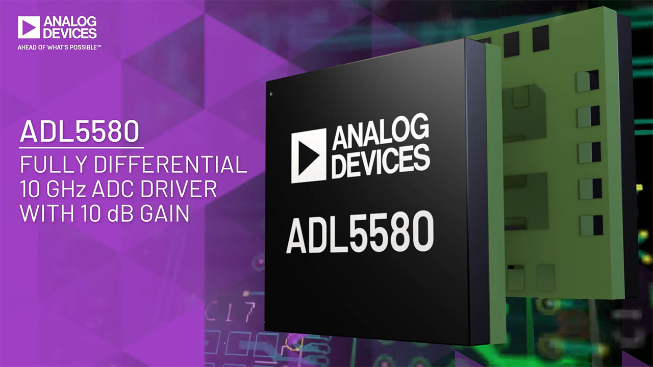
ADL5580
Fully Differential, 10 GHz ADC Driver with 10 dB Gain
Show More
Not the part you were looking for?
Ask a Question
Submit your question below and we will return the best answer from ADI’s knowledge database:
Other places you can find help
Support
Analog Devices Support Portal is a one-stop shop to answer all your ADI questions.
Visit the ADI Support PageFeatures
- −3 dB bandwidth: 10.0 GHz
- Preset 10 dB gain, can be reduced by adding external resistors
- Differential or single-ended input to differential output
- Internally dc-coupled inputs and outputs
- Input voltage noise (NSD, RTI): 2.25 nV/√Hz at 100 MHz
- Low noise input stage: 11.3 dB noise figure at 1 GHz
- Low distortion with +5.0 V and −1.8 V supplies and 1.4 V p-p
- output differential with a 50 Ω||1 pF load differential
- 2 GHz: −59.4 dBc (HD2), −54.3 dBc (HD3), −68.2 dBc (IMD3)
- 6 GHz: −66 dBc (HD2), −88.1 dBc (HD3), −48.3 dBc (IMD3)
- 276 mA positive supply current at 5.0 V typical
- −224 mA negative supply current at −1.8 V typical
- Power disable
The ADL5580 is a high performance, single-ended or differential amplifier with 10 dB of voltage gain, optimized for applications spanning from dc to 10.0 GHz. The amplifier offers a low referred to input (RTI) noise spectral density (NSD) of 2.24 nV/√Hz (at 1000 MHz) and is optimized for distortion performance over a wide frequency range, making the device an ideal driver for high speed 12-bit to 16-bit analog-to-digital converters (ADCs). The ADL5580 is suited for use in high performance, zero intermediate frequency (IF), and complex IF receiver designs. In addition, this device has low distortion for single-ended input driver applications.
By using two external series resistors, the gain selection from 10 dB for a differential input can be modified to a lower gain. The device maintains low distortion through its output common-mode voltage (VCM) of 0.5 V, providing a flexible capability for driving ADCs with full-scale levels up to 1.4 V p-p.
Operating from a +5 V and −1.8 V supply, the positive and negative supply current of the ADL5580 is typically +276 mA and −224 mA, respectively. The device has a power disable feature, and when disabled, the amplifier consumes 2 mA.
The ADL5580 is optimized for wideband, low distortion, and low noise operation at the dc to 10.0 GHz frequency range. These attributes, together with its adjustable gain capability, make this device an optimal choice for driving a wide variety of ADCs, mixers, pin diode attenuators, surface acoustic wave (SAW) filters, and a multiplicity of discrete RF devices.
Fabricated on an Analog Devices, Inc., high speed silicon germanium (SiGe) process, the ADL5580 is supplied in a compact 4 mm × 4 mm, 20-terminal land grid array (LGA) package and operates over the −40°C to +85°C temperature range.
APPLICATIONS
- Instrumentation and defense applications
Ask a Question
Submit your question below and we will return the best answer from ADI’s knowledge database:
Other places you can find help
Support
Analog Devices Support Portal is a one-stop shop to answer all your ADI questions.
Visit the ADI Support Page{{modalTitle}}
{{modalDescription}}
{{dropdownTitle}}
- {{defaultSelectedText}} {{#each projectNames}}
- {{name}} {{/each}} {{#if newProjectText}}
- {{newProjectText}} {{/if}}
{{newProjectTitle}}
{{projectNameErrorText}}
ADL5580
Documentation
Filters
1 Applied
Data Sheet
2
User Guide
1
Documentation
Product Selection Guide 1
Thought Leadership Page 1
Webcast 1
Video
1
ADI has always placed the highest emphasis on delivering products that meet the maximum levels of quality and reliability. We achieve this by incorporating quality and reliability checks in every scope of product and process design, and in the manufacturing process as well. "Zero defects" for shipped products is always our goal. View our quality and reliability program and certifications for more information.
Part Model | Pin/Package Drawing | Documentation | CAD Symbols, Footprints, and 3D Models |
---|---|---|---|
ADL5580BCCZ-R7 | 20-Terminal LGA (4mm x 4mm x 0.81mm) |
|
- ADL5580BCCZ-R7
- Pin/Package Drawing
- 20-Terminal LGA (4mm x 4mm x 0.81mm)
- Documentation
- HTML Material Declaration
- HTML Reliablity Data
- CAD Symbols, Footprints, and 3D Models
- Ultra Librarian
- SamacSys
Software & Part Ecosystem
Device Drivers
API Device Drivers
Device Application Programming Interface (API) C code drivers provided as reference code that allows the user to quickly configure the product using high-level function calls. The library acts as an abstraction layer between the application and the hardware. The API is developed in C99 to ensure agnostic processor and operating system integration. Customers can port this application layer code to their embedded systems by integrating their platform-specific code base to the API HAL layer.
To request this software package, go to the Software Request Form signed in with your MyAnalog account and under “Target Hardware” select “High Speed RF Products” and choose the desired API product package. You will receive an email notification once the software is provided to you.
Looking for Evaluation Software? You can find it here
Parts | Product Life Cycle | Description | ||
---|---|---|---|---|
Standard High Speed A/D Converters2 |
||||
RECOMMENDED FOR NEW DESIGNS |
12-Bit, 6 GSPS/10.25 GSPS, RF Analog-to-Digital Converter |
|||
RECOMMENDED FOR NEW DESIGNS |
12-Bit, 10.25 GSPS, JESD204B, RF Analog-to-Digital Converter |
Evaluation Kits 1
EVAL-ADL5580
ADL5580-EVALZ Evaluation Board
Product Detail
The ADL5580-EVALZ evaluation board allows the manual control of the ADL5580 through the USB port on a Windows® PC via a SDP-S interface board.
Additional information on the ADL5580 is provided in the ADL5580 data sheet. Consult the ADL5580 data sheet in conjunction with the user guide when using the ADL5880-EVALZ evaluation board.