ADIN1110
Robust, Industrial, Low Power 10BASE-T1L Ethernet MAC-PHY
Show More
Not the part you were looking for?
Ask a Question
Submit your question below and we will return the best answer from ADI’s knowledge database:
Other places you can find help
Support
Analog Devices Support Portal is a one-stop shop to answer all your ADI questions.
Visit the ADI Support PageFeatures
- 10BASE-T1L IEEE Standard 802.3cg-2019 compliant
- Cable reach up to 1700 m with 1.0 V/2.4 V
- Integrated MAC with SPI
- Supports OPEN Alliance 10BASE-T1x MAC-PHY serial interface
- 16 MAC address filters
- High and low priority queues with 28 kB buffer
- Cut through or store forward operation
- IEEE 1588 timestamp support
- Statistics counters
- Low power consumption: 42 mW (dual-supply, 1.0 V p-p)
- Diagnostics
- Cable fault detection with TDR
- Link quality indicator with MSE
- Frame generator and checker
- Multiple loopback modes
- IEEE test mode support
- Supports 1.0 V p-p and 2.4 V p-p transmit levels
- 4-pin MDI (RXN, RXP, TXN, and TXP)
- Suitable for intrinsic safety applications
- External termination resistors
- Autonegotiation
- 25 MHz crystal or external clock input
- Electromagnetic compatibility (EMC) test standards
- IEC 61000-4-4 electrical fast transient (±4 kV)
- IEC 61000-4-2 ESD (±4 kV contact discharge)
- IEC 61000-4-2 ESD (±8 kV air discharge)
- IEC 61000-4-6 conducted immunity (10 V/m)
- IEC 61000-4-5 surge (±4 kV)
- IEC 61000-4-3 radiated immunity (Class A)
- EN55032 radiated emissions (Class B)
- Small package: 40-lead (6 mm × 6 mm) LFCSP
- Temperature range
- Industrial: −40°C to +85°C
- Extended: −40°C to +105°C
The ADIN1110 is an ultra low power, single port, 10BASE-T1L transceiver design for industrial Ethernet applications and is compliant with the IEEE® 802.3cg-2019™ Ethernet standard for long reach, 10 Mbps single pair Ethernet (SPE). Featuring an integrated media access control (MAC) interface, the ADIN1110 enables direct connectivity with a variety of host controllers via a 4-wire serial peripheral interface (SPI). This SPI enables the use of lower power processors without an integrated MAC, which provides for the lowest overall system level power consumption. The SPI can be configured to use the Open Alliance SPI protocol or a generic SPI protocol.
The programmable transmit levels, external termination resistors, and independent receive and transmit pins make the ADIN1110 suited to intrinsic safety applications.
The ADIN1110 has an integrated voltage supply monitoring and power-on reset (POR) circuitry to improve system level robustness.
The ADIN1110 is available in a 40-lead, 6 mm × 6 mm lead frame chip scale package (LFCSP).
APPLICATIONS
- Field instruments
- Building automation and fire safety
- Factory automation
- Edge sensors and actuators
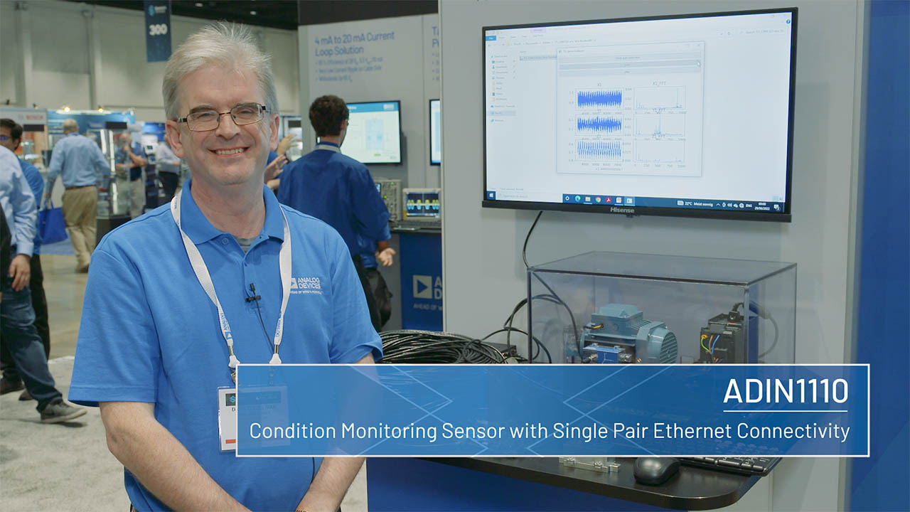
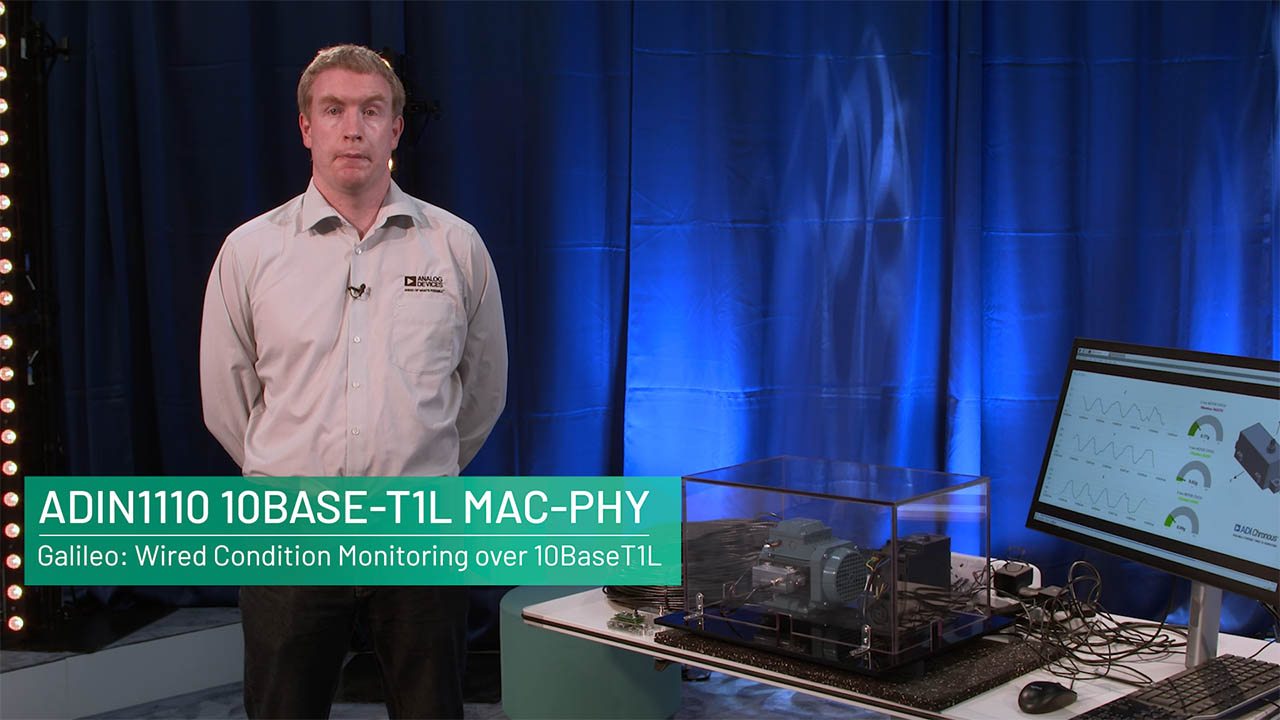
- Condition monitoring and machine connectivity
Want to get started developing a 10BASE-T1L Solution?
Why not email our team of experts to get samples of the ADIN1110 or an evaluation board.
Ask a Question
Submit your question below and we will return the best answer from ADI’s knowledge database:
Other places you can find help
Support
Analog Devices Support Portal is a one-stop shop to answer all your ADI questions.
Visit the ADI Support Page{{modalTitle}}
{{modalDescription}}
{{dropdownTitle}}
- {{defaultSelectedText}} {{#each projectNames}}
- {{name}} {{/each}} {{#if newProjectText}}
- {{newProjectText}} {{/if}}
{{newProjectTitle}}
{{projectNameErrorText}}
ADIN1110
Documentation
Filters
1 Applied
Data Sheet
2
User Guide
1
WIKI
Technical Articles
24
HTML
HTML
HTML
HTML
HTML
HTML
HTML
HTML
HTML
HTML
HTML
HTML
HTML
HTML
HTML
HTML
HTML
HTML
HTML
HTML
HTML
HTML
HTML
HTML
Application Note
1
HTML
Documentation
Data Sheet 1
User Guide 1
Application Note 1
Technical Articles 8
Device Drivers 3
Solutions Bulletin & Brochure 1
Thought Leadership Page 4
Webcast 3
Video
5
ADI has always placed the highest emphasis on delivering products that meet the maximum levels of quality and reliability. We achieve this by incorporating quality and reliability checks in every scope of product and process design, and in the manufacturing process as well. "Zero defects" for shipped products is always our goal. View our quality and reliability program and certifications for more information.
Part Model | Pin/Package Drawing | Documentation | CAD Symbols, Footprints, and 3D Models |
---|---|---|---|
ADIN1110BCPZ | 40-Lead LFCSP (6mm x 6mm x 0.75mm) |
|
|
ADIN1110BCPZ-R7 | 40-Lead LFCSP (6mm x 6mm x 0.75mm) |
|
|
ADIN1110CCPZ | 40-Lead LFCSP (6mm x 6mm x 0.75mm) |
|
|
ADIN1110CCPZ-R7 | 40-Lead LFCSP (6mm x 6mm x 0.75mm) |
|
- ADIN1110BCPZ
- Pin/Package Drawing
- 40-Lead LFCSP (6mm x 6mm x 0.75mm)
- Documentation
- HTML Material Declaration
- HTML Reliablity Data
- CAD Symbols, Footprints, and 3D Models
- Ultra Librarian
- SamacSys
- ADIN1110BCPZ-R7
- Pin/Package Drawing
- 40-Lead LFCSP (6mm x 6mm x 0.75mm)
- Documentation
- HTML Material Declaration
- HTML Reliablity Data
- CAD Symbols, Footprints, and 3D Models
- Ultra Librarian
- SamacSys
- ADIN1110CCPZ
- Pin/Package Drawing
- 40-Lead LFCSP (6mm x 6mm x 0.75mm)
- Documentation
- HTML Material Declaration
- HTML Reliablity Data
- CAD Symbols, Footprints, and 3D Models
- Ultra Librarian
- SamacSys
- ADIN1110CCPZ-R7
- Pin/Package Drawing
- 40-Lead LFCSP (6mm x 6mm x 0.75mm)
- Documentation
- HTML Material Declaration
- HTML Reliablity Data
- CAD Symbols, Footprints, and 3D Models
- Ultra Librarian
- SamacSys
Software & Part Ecosystem
Device Drivers
Looking for Evaluation Software? You can find it here
Can't find the software or driver you need?
Request a Driver/SoftwareEvaluation Kits 3
AD-APARD32690-SL
Arduino Form-factor Development Platform Based on MAX32690 ARM Cortex-M4 Microcontroller
Product Detail
The AD-APARD32690-SL is a platform for prototyping intelligent, secure, and connected field devices. It has an Arduino Mega-compatible form factor and two Pmod™-compatible connectors.
The system includes the MAX32690 ARM Cortex-M4 with FPU-Based Microcontroller and Bluetooth LE 5.2. The MCU is coupled with external RAM (2 x 512 Mb) and Flash (64 Mb) memories to meet the requirements of the most demanding applications. The MAXQ1065 security coprocessor enables state of the art security features such as for root-of-trust, mutual authentication, data confidentiality and integrity, secure boot, and secure communications.
A 10 Mbps single-pair Ethernet link using the ADIN1110 10BASE-T1L MAC/PHY, enables remote data acquisition and system configuration. The 10BASE-T1L interface also supports Single-pair Power over Ethernet (SPoE) and be used for powering the system via an Arduino shield implementing the required power circuitry.
WiFi connectivity is provided via the on-board NINA-W102 multiradio wireless MCU module with internal antenna.
Power can be supplied either via the USB-C connector or via a 2-pin terminal block. The supported input voltage range is 5 V to 28 V.
The system is accompanied by an open-source software stack and associated collateral, enabling a complete experience from evaluation, and prototyping, all the way to production firmware and application development. The open-source software stack also includes drivers and example applications for a wide variety of ADCs, DACs, sensors, and other devices commonly used in industrial applications, further accelerating the development process. An external programmer such as the MAX32625PICO DAPLink, or any other similar programmer supporting the SWD interface, enables firmware programming and debug. The system’s firmware is based on Analog Devices’ open-source no-OS framework which includes all the tools required for embedded code development and debugging as well as libraries, enabling host-side connectivity for system configuration and data transfer over the UART, USB, WiFi, and 10BASE-T1L interfaces.
APPLICATIONS
- Factory automation
- Process control
- Intelligent buildings
- Secure field instruments
- Internet of Things
Resources
AD-SWIOT1L-SL
Software-configurable Analog and Digital I/O with 10BASE-T1L Evaluation and Development Platform
Product Detail
The AD-SWIOT1L-SL provides a complete software and hardware platform for prototyping intelligent, secure, network capable field devices.
The design incorporates the AD74413R Quad-Channel, Software Configurable Input and Output and the MAX14906 Quad-Channel Industrial Digital Output/Digital Input ICs, allowing the multiplexing of several analog and digital functions on four channels which can be independently configurable through software to act as:
- voltage output / input
- current output / input
- digital input / output
- RTD measurement
A 10 Mbps single-pair Ethernet link, using the ADIN1110 10BASE-T1L MAC/PHY, enables remote data acquisition and device configuration. The 10BASE-T1L interface can also be used for powering the system via the Single-pair Power over Ethernet (SPoE) technology using the LTC9111 Powered Device (PD) controller. This way, power and data for the system is provided over the same cable to significantly simplify the cabling infrastructure and cost.
For applications requiring high current capabilities, the system can be powered from an external 24 V supply and up to 1.2 A can be output on any of the channels configured as digital outputs. The power supply solution also includes the ADP1032 high performance, isolated micropower management unit (PMU) to provide power and digital control for software configurable I/O devices in one of the most compact formats. The LT8304 Micropower No-Opto Isolated Flyback Converter completes the power tree to provide isolated power to the digital part of the design.
The on-board MAX32650 Ultralow Power ARM® Cortex®-M4 Microcontroller exposes all the necessary debug and programming features to enable a complete software development experience with the system. It is coupled with a 1 Gb (128 MB) external RAM and a 64 Mb (8 MB) external flash memory to meet the most demanding applications and provide the flexibility to implement any protocol stack. Security features are enabled by the MAXQ1065 security coprocessor.
The system is accompanied by an open-source software stack and associated collateral, enabling a complete experience from evaluation and prototyping all the way to production firmware and applications development. An external programmer such as the MAX32625PICO MAXDAP Programming Adapter, or any other similar programmer supporting the SWD interface, is required to enable firmware programming and debug. The system’s firmware is based on Analog Devices’ open-source no-OS framework which includes all the tools required for embedded code development and debugging as well as libraries enabling host-side connectivity for system configuration and data transfer over the UART or the 10BASE-T1L interfaces. A PC application with a user-friendly graphical interface is provided to enable easy system configuration and displaying the acquired data in different ways.
I/O | |
Channels | 4 Software Configurable IO channels |
Digital input | Type 1 and 3, or Type 2 |
Digital output | High-Side (HS) Switch or Push-Pull (PP) Driver |
Analog input | Voltage (0 V to 10 V), Current (0 mA to 25 mA) |
Analog output | Voltage (0 V to 11 V), Current (0 mA to 25 mA) |
RTD measurements | 2-wire RTD (0 Ω to 1 MΩ) |
Computing Resources | |
CPU | MAX32650 Ultra-Low-Power Arm Cortex-M4 with FPU-Based Microcontroller (MCU) with 3 MB Flash and 1MB SRAM |
Memory | 1 Gb RAM |
Storage | 64 Mb QSPI Flash |
Connectivity | |
Ethernet | 10BASE-T1L |
Power Supply | |
External power | 24 DC @ 6A |
Power over Ethernet | SPoE class 12 |
Operating Conditions | |
Temperature range | -25°C to 60°C |
Resources
EVAL-ADIN1110
Evaluating the ADIN1110 Robust, Industrial, Low Power 10BASE-T1L Ethernet MAC-PHY
Product Detail
The EVAL-ADIN1110EBZ is a flexible platform enabling quick evaluation of the ADIN1110, robust, low power 10BASE-T1L MAC-PHY. It provides 10Mbit per second Single Pair Ethernet (SPE) connections with devices across 1.7km of cable.
The evaluation board offers two modes of operation for maximum flexibility. Connected to a PC via USB port, the full set of ADIN1110 register settings and features such as link quality monitoring and diagnostics can be accessed over the USB using serial command interface. The board also provides an Arduino interface.
Alternatively, the board can operate in stand-alone mode where it is configured by setting hardware configuration links and switches. On-board LEDs provide status indication.
The SPI interface provides configuration and data access to the ADIN1110.
A small prototyping area and test points are provided for experimentation with alternative cable connection topologies including isolation transformers and/or power coupling inductors.
Resources
Evaluation Kits3
Tools & Simulations 1
IBIS Model 1
Reference Designs 1
CN0575
10BASE-T1L Field Device Development Platform with Class 12 and 13 SPoE