Testing Data Converters with the Arrow/Altera SoCkit FPGA Board
Introduction
This blog describes how Analog Devices is using the SoCkit Cyclone V SoC FPGA board from Arrow Electronics as a system for evaluating medium-speed data converters: ADCs, DACs with sample rates less than 100Msps. LTCmanufactures several evaluation boards for this purpose, including the DC718, DC890, and DC1371. These boards work well, and tight integration with the supporting software makes them nearly foolproof. However, customers often run into their limitations - limited memory (by modern standards), and lack of extra resources that would potentially make them useful for developing FPGA code. The SoCkit board promises to expand upon the capabilities of these systems by providing much deeper memory, the ability to easily modify FPGA code, and streamlined communication to the host computer. This board also serves as a platform for testing customer-facing FPGA code.
The Linduino system is worth mentioning here because it provides a similar function for lower speed data converters and other products that are more likely to be interfaced to a microcontroller than an FPGA. Prior to the Linduino, LTC's low-speed converter evaluation boards used the DC590B interface board, which has a PIC microcontroller running "closed-source" firmware. The Arduino is an extremely popular open-source platform for microcontrollers, with a free development environment. Its popularity and availability make it a natural choice to base a converter evaluation system on.
The Linduino system could have been based on a number of different microcontrollers. It just so happens that the existing Arduino ecosystem allowed LTC to sidestep the problem of setting up the programming environment, compiler, bootloader, and other items related to "just getting started". No such ecosystem exists for FPGA code development. (There have been some attempts, but none coming close to the convenience of Arduino for microcontrollers…)
The challenge for an analogous FPGA-based system then becomes how to design a system that uses proprietary, vendor specific tools and make it as useful and convenient as possible to our customers, regardless of the tools that they are using in their designs. The Arrow SoCkit FPGA evaluation board is a suitable choice.
Some of the parallels between the Linduino and SoCkit system are:
- The SoCkit, like the Linduino, acts as a communication bridge between a product's demo board and part-specific evaluation software (provided by Analog Devices) running on a host computer
- The SoCkit, like the Linduino, allows customers to communicate with product demo boards from their own software, written in C, Matlab, Python, etc., through a simple interface.
- The SoCkit, like the Linduino, provides a uniform hardware test platform for part-specific "driver" code, written in generic Verilog (C for the Linduino), that is designed to be portable to other FPGAs (microcontrollers for Linduino code)
Some customers may happen to be using the same FPGA family that is used on the SoCkit, and thus may be able to extract additional benefit.
"Hello, World!", FPGA style
This system has lots of moving parts, so we'll take it a step at a time and save the details for later. Fundamentally, we need the ability to easily write to and read back registers in the FPGA from a host computer. And a wise man1 once said, "If you can blink a light, you can do anything", So let's map a light to an FPGA register and blink it. The first step is to boot the SoCkit board using Analog Devices' SD card image. The image is available here: http://www.analog.com/media/en/evaluation-boards-kits/evaluation-software/LT_SoCkit_latest_SDcard_image.zip and can be written to a 4GB or larger SD card. (A high-quality, brand-name card, class 10 or faster, is recommended.) Writing the image is a straightforward procedure, documented specifically for the SoCkit board here: https://rocketboards.org/foswiki/view/Documentation/ArrowSoCKITEvaluationBoardLinuxGettingStarted
This is identical to the procedure for writing images for other popular small Linux boards, such as the Raspberry Pi. The Raspberry Pi page includes instructions for Mac OS as well as Windows and Linux.
https://www.raspberrypi.org/documentation/installation/installing-images/
Once the SD card is written, insert it into the SoCkit board, and connect the SoCkit board to a LAN that has a DHCP server. (Direct connection will be described later.) Make sure that SW6 is set as shown below. (An incorrect setting will not allow the board to boot.)
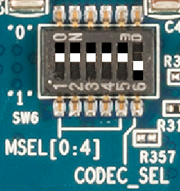
Turn on the power, and after ~30 seconds, the assigned IP address will appear in the LCD screen. As part of the boot process, a default FPGA configuration file is loaded into the FPGA side of the SoC device.
The next step is to get the code that will run on the host computer. Install LinearLabTools from: http://www.analog.com/en/design-center/evaluation-hardware-and-software/evaluation-platforms/linearlab-tools
Run this script, with the IP address as a command line argument: \linear_lab_tools64\python\llt\app_examples\Hello_World\SoCkit_hello_world.py
For example: python SoCkit_hello_world.py "10.54.6.123"
All FPGA loads for this system (including the default load) have LED[0] wired to the same point in the design, so this script will work with any of the provided loads. That's it... we've blinked a light, so we can do anything!
Blinking a light represents the simplest "writing" operation. Each FPGA load also has a hardcoded "Type" and revision that can be read back. This is to give the host computer a way to verify that the correct FPGA configuration is loaded. Notice that the script also prints out the FPGA type and revision in the console, which represents the simplest "reading" operation.
Communicating with the FPGA does not get much more complicated than this. More involved operations such as initiating data capture, configuring options, and reading back status signals, are made up of these basic reading and writing commands.
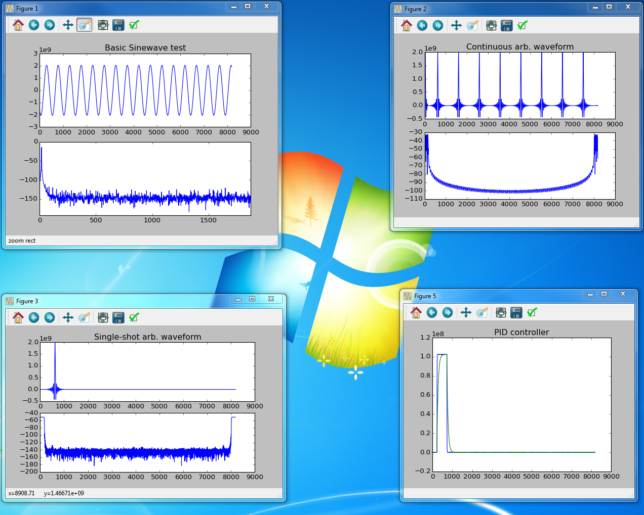
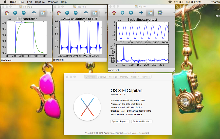
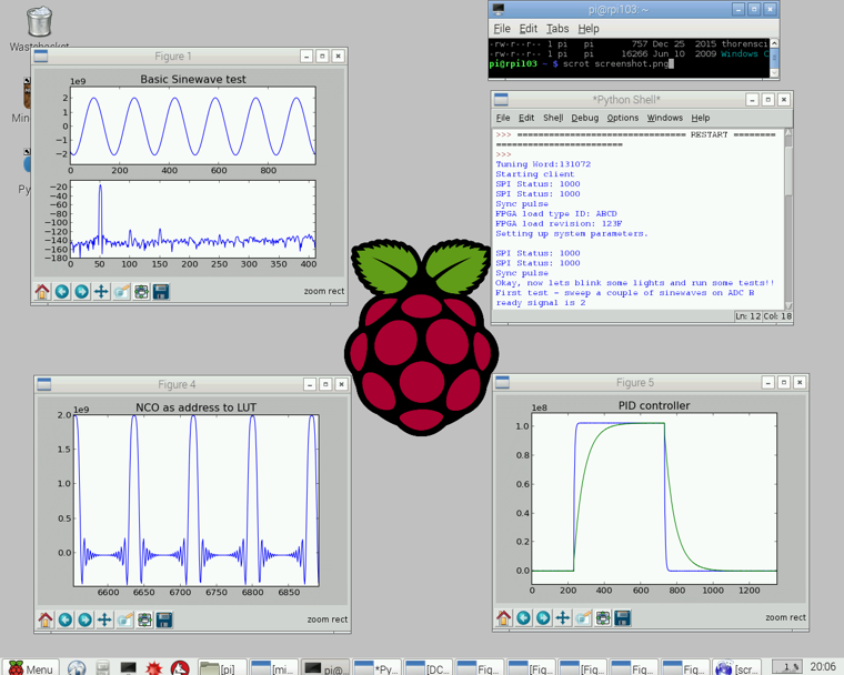
Before moving on to more exciting things, let's demonstrate another attractive aspect of this system: platform independence. Because this is a generic Ethernet connection, there are no issues with drivers and compatibility. And Python itself is highly cross platform - the screenshots below show the output from a test script for the DC2390, a SoCkit-compatible board for the LTC2500-32 oversampling SAR ADC running on...
Windows:
Mac:
And a Raspberry Pi:
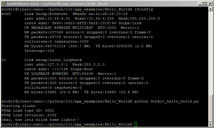
And... you can log into the SoCkit board itself via SSH and run scripts that don't use graphics. This can be useful for setting up tests that need to run autonomously, with no intervention from a host computer. The screenshot below is the output from the "SoCkit_hello_world.py" script (that blinks a light.) Note that no command line argument was given, so the script defaults back to the local loopback IP address of 127.0.0.1.
1) Professor Bruce Segee, University of Maine EE department
Testing an Analog to Digital Converter
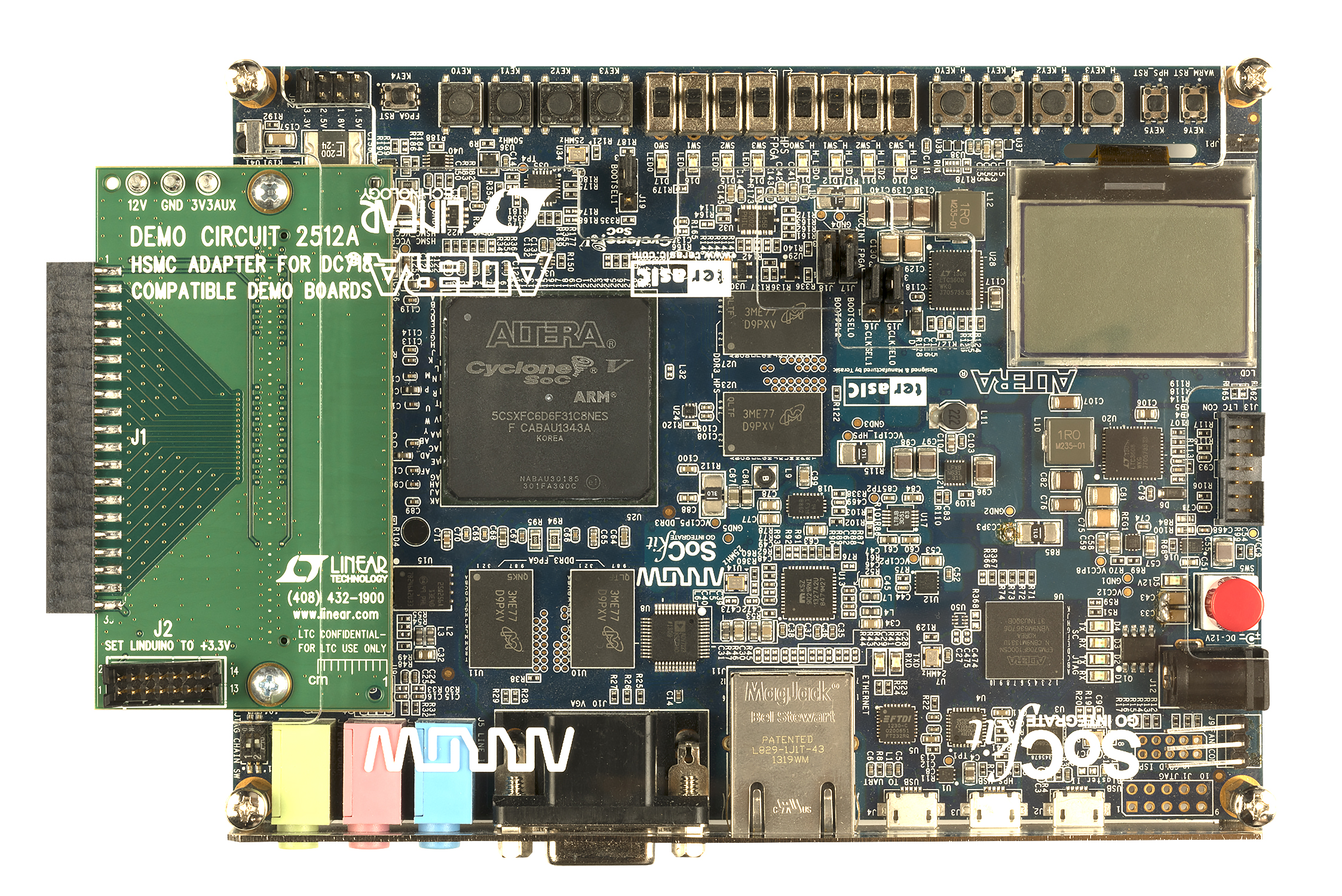
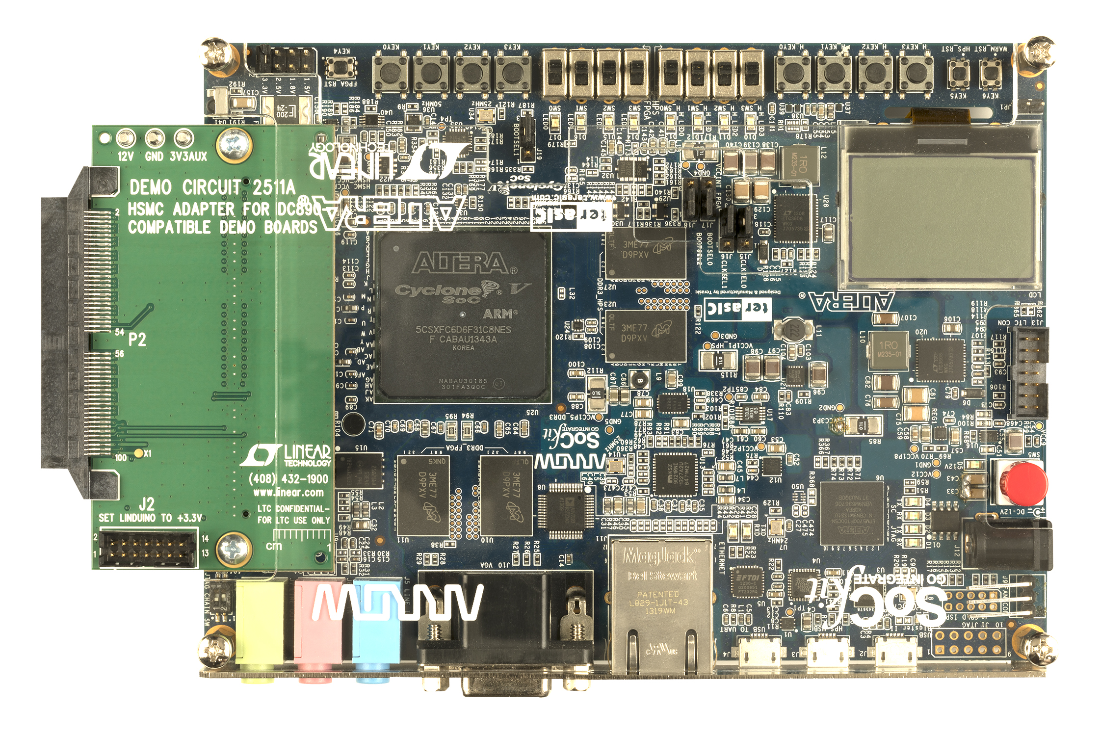
With light blinking out of the way, let's do something useful and capture data from a single-channel ADC. Two adapter boards are available that allow a subset of Analog Devices' ADC demo boards to interface with the SoCkit. DC2511 works with demo boards that use the DC890 data capture board, and DC2512 works with demo boards that use the DC718 data capture board.
DC2512 for DC718-compatible eval boards
DC2511 for DC890-compatible eval boards
A "default FPGA configuration" was mentioned above. The Linux image has several FPGA configuration files that can be loaded into the FPGA side of the SoC, depending on which board is connected to the SoCkit. The default file is called "cmos_32bit_capture.rbf", which, as the name would imply, captures 32-bit wide data from an attached board. The DC2511 and DC2512 both use this configuration for a number of ADC demo boards, with various subsets of the 32-bits used.
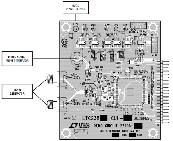
The LTC2387-18 is a state-of-the-art 15Msps SAR ADC with exceptionally low noise and linearity error. Its evaluation board, the DC2290, deserializes the ADC's output and provides parallel data to a DC718 capture board.
To set up this experiment, connect the DC2290A-A as described in its demo manual, then mate the edge connector to the DC2512 adapter on the SoCkit:
Then run the test script for this setup, DC2512_basic_capture.py, located in:
\linear_lab_tools64\python\llt\demo_board_examples\dc2512\
The script is configured to take a 16 megasample data record. Unfortunately the Matplotlib plotting routine requires too much memory to plot this amount of data. In order to get an approximation of the shape, the script downsamples the data record by a factor of 64, which is shown in the plot below. This plot was taken with a 10Hz analog input frequency, and represents a 1.12 second long data capture at the full 15Msps sample rate of the LTC2387-18.

While the plot is downsampled, the full data record is available for analysis or processing.
At 15Msps, the DC718's maximum capture depth of 256k only represents 17.4 milliseconds. The lowest frequency that can be analyzed is 57.2Hz, obscuring low-frequency effects that are important in many applications. The 16 megasample shown above allows frequencies as low as 0.89Hz to be analyzed, impossible with the DC718.
Testing a Dual ADC
Another popular ADC with applications that benefit from deep memory is the LTC2323 dual, 16-bit, 5Msps ADC. The DC1996A-A demo board is compatible with the DC890 capture board, so a DC2511 is used to interface to the SoCkit board.
To set up this experiment, connect the DC1996A-A as described in its demo manual, then mate the edge connector to the DC2511 adapter on the SoCkit:
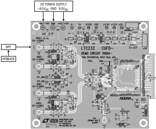
Similarly, running this script:
\linear_lab_tools64\python\llt\demo_board_examples\dc2511\DC2511_basic_capture.py
will capture a block of data, and generate time and frequency domain plots.
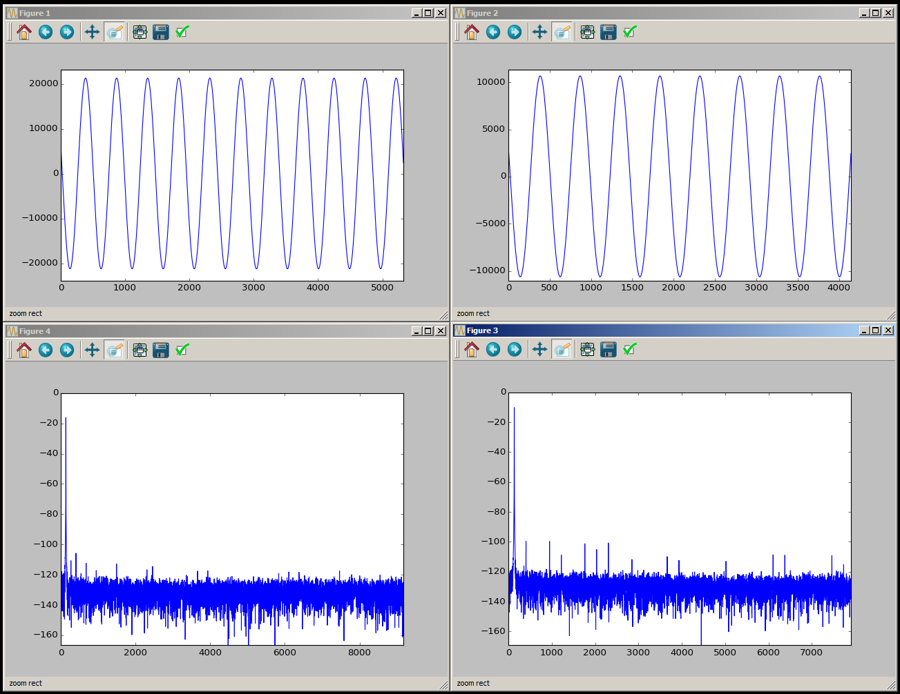
Once again, with 256M samples per channel, applications requiring analysis of very low frequencies or sparse time-domain events are easily evaluated.
Connection via USB
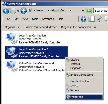
It may not always be possible to connect the SoCkit board to a local network - the network administrator may not allow it, and many laptop computers do not have an ethernet jack at all. A USB to Ethernet adapter can be used to connect a host computer directly to the SoCkit. When the SoCkit boots, Linux first attempts to obtain a network connection via DHCP. If this fails, it falls back to a static address of 192.168.1.231. On the host computer, a USB to Ethernet adapter can be configured with a static address. First, locate the adapter under network settings, and select properties.
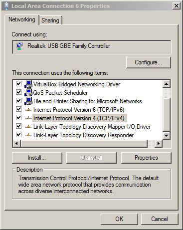
Highlight "Internet Protocol Version 4 (TCP/IPv4)", then click Properties:
And finally, enter the following static IP address configuration:
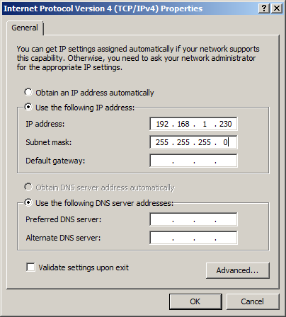
(Note that the last octet must be something other than 231, the SoCkit's address)
The SoCkit board can now be accessed from the host PC at address 192.168.1.231. The procedure is similar for Linux and Mac systems.
Conclusion
The SoCkit board, along with LinearLabTools and DC2511/12, provides a flexible tool for data converter evaluation that is much more capable than existing capture boards. Ethernet communication requires no additional driver support, and is compatible with any modern operating system.


