Scalable LCR Measurement in ATE Systems Through Probe-Card-Level Integration

Scalable LCR Measurement in ATE Systems Through Probe-Card-Level Integration
著者
Lydia Chen
2026年09月04日
Key Takeaways
|
Abstract
Semiconductor testing is moving toward higher complexity and parallelism, increasing the need for inductance, capacitance, and resistance (LCR) measurements in high-site-count automatic test equipment (ATE) and SiC/GaN testing. However, external bench-top LCR meters and cable-based setups are difficult to scale and can reduce repeatability. This article introduces an embedded, modular LCR approach and a probe-card integration case enabling scalable, parallel LCR testing, with an outlook on future ATE applications.
Market Background and Application Trends
In recent years, semiconductor test requirements have shifted toward higher complexity and higher parallelism, driven by advanced packaging adoption, increasing integration density, and growing need for power and signal integrity validation. As a result, wafer-level and package-level testing now includes more parametric characterization beyond basic pass/fail.
Among these parametric needs, inductance, capacitance, and resistance (LCR) measurement has become increasingly important because it provides fast, quantitative impedance characterization of passive components and device structures. This trend is especially visible in automatic test equipment (ATE) environments, where customers push for higher site counts and faster throughput, creating demand to migrate traditionally bench-top measurements into scalable, production-ready architectures.
In Taiwan, the increasing adoption of wide-band-gap power devices such as silicon carbide (SiC) and gallium nitride (GaN) requires characterization of impedance-related parameters, including gate capacitance and turn-on resistance, which impact switching performance, efficiency, and reliability.
However, many ATE platforms do not natively support LCR measurements, so customers often rely on external bench-top LCR meters connected via cables and fixtures. This approach is typically single-site and difficult to scale, and long interconnect paths can reduce repeatability and increase integration overhead.
This article introduces an embedded, modular LCR approach and shares a successful customer case in Taiwan, where the ADI LCR solution (EVAL-ADMX2001) was integrated directly onto the probe card, replacing a bench-top setup and enabling scalable, parallel LCR testing in an ATE system. In the end, future successful cases for new ATE-related applications will also be mentioned.
LCR Measurement Principles in ATE Environments
LCR measurements are widely used to characterize passive components and device structures by extracting impedance magnitude and phase at a given stimulus frequency. In typical implementations, an LCR measurement system can be viewed as three functional blocks: AC stimulus generation, voltage and current sensing, and magnitude/phase extraction.
Basic Measurement Concept
A practical LCR measurement setup generally follows this signal flow.
- AC Stimulus Generation: The system applies a known sinusoidal (or periodic) stimulus across the device under test (DUT).
- Sensing: The system measures the resulting voltage and current response.
- Extraction: Using the measured magnitude and relative phase between voltage and current, the system estimates complex impedance Z, and derives equivalent R, L, and C values under the chosen measurement model (for example, series or parallel representation).
For a sinusoidal stimulus at frequency f(ω=2πf), the DUT impedance is computed in the phasor domain as

If the measured magnitudes are ∣V∣ and ∣I∣, and the phase difference is ϕ=∠V-∠I, then

where 𝑅 is the resistive component and 𝑋 is the reactive component (Figure 1).
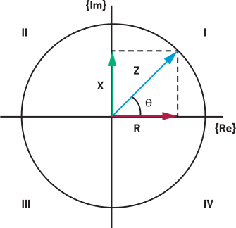
Results are commonly reported using a series model 𝑍 = 𝑅𝑠 + 𝑗𝑋𝑠 (often preferred for low-impedance DUTs) or a parallel model via admittance.

This is typically useful for higher-impedance/leakage-dominant cases.
Why Measurement Path Length Matters
In ATE deployments, the impedance measurement signal path typically includes additional interconnect elements, such as cables, connectors, switching networks, and probe card routing between the measurement module and the DUT. These elements introduce parasitics that affect both the measured impedance magnitude and phase, and their impact generally increases with path length and integration complexity.
- Parasitic Resistance (R): Adds series loss and can bias low-impedance measurements.
- Parasitic Inductance (L): Becomes more prominent as frequency increases and can distort phase response.
- Parasitic Capacitance (C): Couples nodes and can create frequency-dependent loading effects, particularly for highimpedance measurements.
As a result, longer module-to-DUT paths tend to increase measurement uncertainty and reduce repeatability, especially when a bench-top LCR meter is remotely connected to the DUT through cables and fixtures. From a system perspective, it is important to recognize that LCR measurement is inherently phase-sensitive; therefore, any added parasitics or signal integrity degradation along the stimulus and sensing paths can translate directly into measurable error and variability.
Lab Instrument vs. ATE Reality
Bench-top LCR meters are designed to deliver high accuracy in a well-controlled lab setup. In an ATE environment, the same measurement becomes harder because the system must work under additional real-world constraints:
- More Switching and Routing: Signals often travel through switches and complex routing, which adds parasitics and increases variation.
- Limited Space Near the DUT: On a probe card, area, routing density, and thermal limits restrict where measurement circuits can be placed.
- Production Priorities: ATE emphasizes throughput, multisite parallel testing, and scalability, which may not align with a single-channel, maximum-accuracy lab instrument approach.
As a result, success in ATE is not just about achieving good accuracy in one setup. It requires an architecture that can still deliver stable, repeatable results and maintain reasonable correlation to a reference instrument while scaling to multisite operation.
System-Level Comparison for LCR Measurement in ATE
When deploying LCR measurements in ATE systems, the core challenge is balancing measurement fidelity with scalable test throughput. Unlike lab environments where the primary goal is accuracy for a single setup. ATE requires an architecture that supports high channel density and parallel testing while maintaining sufficient correlation to reference measurements. Table 1 shows the key engineering comparison between conventional bench top equipment vs. a modular approach for ATE application.
| Bench-Top LCR Meter (Cable-Based) | Embedded Modular LCR | Practical Implication in ATE | |
| Measurement Path | Long cable and connectors | Short path near DUT | Shorter path reduces parasitic uncertainty and improves repeatability |
| Parallelism | Typically single-site; multiplexing is sequential | Naturally scalable to multisite parallel | Parallel measurement improves throughput and reduces overall test time |
| Channel Scalability | Limited by instrument count and switching complexity | Scales by replicating modules per site | Modular replication supports higher channel density with predictable integration effort |
| Integration Effort | High (fixtures, cabling, switching, maintenance) | Lower | Less system overhead accelerates deployment and reduces operational burden |
| Repeatability in Production | Sensitive to cable routing, connectors, environment | Less sensitive due to reduced interconnect | Better stability can reduce correlation maintenance effort over time |
| Expandability | Often case-by-case per setup | Reusable reference architecture | Creates a scalable platform for future ATE test modules and applications |
Implementation Example: ADMX2001 LCR Module
Based on the previous key takeaways, an embedded modular LCR architecture is a practical approach to scale channel density in ATE systems. As an implementation example, ADI’s Instrumentation System Solutions (ISS) Team built an ADMX2001 module, as shown in Figure 2, which is a compact impedance analyzer system-on-module, PCB size 1.5in × 2.5in (38mm × 63.5mm), designed for embedded use with UART and SPI control interfaces. In practice, the module can be evaluated using the EVAL-ADMX2001EBZ carrier board, which provides convenient access to standard LCR-style DUT connections and I/O headers (BNC) that are helpful when transitioning from bench evaluation to system integration.
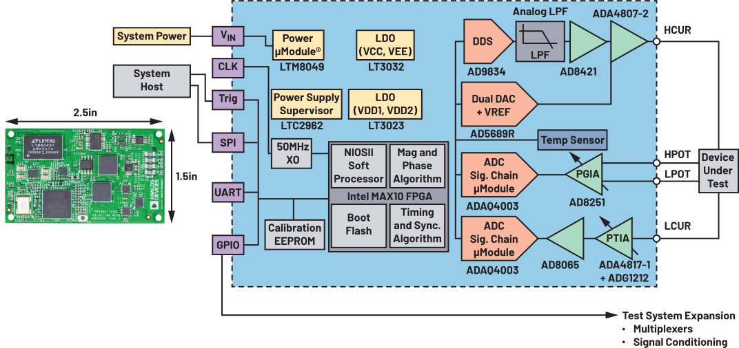
From a measurement topology standpoint, the ADMX2001 supports 4-wire (Kelvin) measurement, separating force and sense paths to minimize lead and contact resistance effects. This is particularly beneficial for low-impedance measurements (for example, equivalent series resistance (ESR)-oriented applications) where small parasitics from cables, connectors, or probe contacts can otherwise bias results. Combined with near-DUT placement, the Kelvin approach helps improve repeatability and reduces sensitivity to path-dependent variation, both of which are important in multisite production screening.
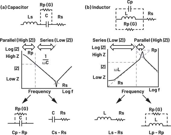
Figure 3 illustrates the complex equivalent circuit of a capacitor and an inductor, which can be extracted via an LCR frequency sweep.
Typical Evaluation-to-Integration Flow
The ADMX2001B module is installed onto the evaluation carrier, powered through the board’s power input, and connected to a host PC via a USB-to-UART cable to access the command-line interface for configuration and measurement execution. For embedded integration, the same platform supports SPI-based control, enabling a host controller (or test executive) to configure measurement conditions, trigger measurements, and read back results in an automated way. Therefore, it is very suitable to integrate with ATE systems.
Calibration Considerations
For practical use, especially when correlating to a bench reference, calibration should be performed after the cabling/fixture/probe configuration is established. A common and effective approach is an open–short–load calibration sequence, which compensates fixture-related parasitics and anchors measurement accuracy using a known reference load. For best correlation, the calibration load is typically chosen to be representative of the expected DUT impedance range at the target frequency points. The platform also supports saving and reusing calibration data for a given fixture configuration. However, if the measurement path or fixture changes materially, recalibration is recommended to maintain stable correlation and repeatability.
Overall, the ADMX2001 module provides a practical embedded building block for scalable LCR measurement: compact enough for near-DUT integration, controllable through ATE-friendly digital interfaces, and supported by a calibration workflow that enables stable correlation to a bench reference under production-oriented constraints.
Successful Customer Case: Probe-Card-Based LCR Measurement in a Multisite ATE Wafer Test System
This section presents a successful customer deployment in Taiwan, where the ADMX2001 LCR modules were integrated into a mainstream multisite ATE environment to enable production-oriented impedance testing. The target application was the measurement of ESR for an automotive-grade specialty capacitor.
Original Setup: External Bench-Top LCR Meter (Cable-Based Configuration)
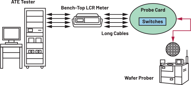
In the customer’s original configuration, as shown in Figure 4, ESR and capacitance measurements relied on an external bench-top LCR meter connected to the DUT region through cables and additional routing. While this approach provided a familiar reference measurement, it introduced practical limitations for ATE usage. The longer interconnect path increased sensitivity to parasitics and phase error contributors, which can be particularly impactful for small ESR measurements. In addition, the measurement flow was largely single-site and sequential, which created a throughput bottleneck compared with other test items that were already optimized for multisite operation.
Migration Strategy: Probe-Card-Based Embedded LCR Modules
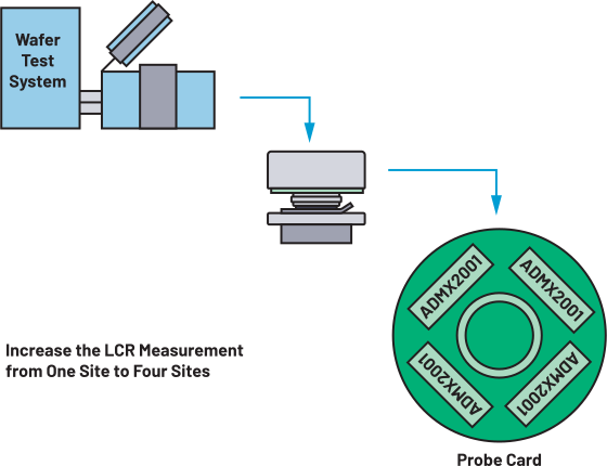
To address these limitations, the customer migrated to a probe-card-based embedded LCR architecture using ADMX2001 modules, as shown in Figure 5. The key system-level change was moving the LCR measurement function closer to the DUT region, thereby shortening the effective measurement path and reducing dependency on long cable runs, also called direct docking. From a production integration standpoint, this helped reduce parasitic uncertainty, improve stability, and simplify the scaling model for multisite testing.
Results: Multisite Enablement and Throughput Improvement
After migration, the LCR measurement capability was scaled from single-site operation to multisite (4 to 8) operation, enabling parallel LCR/ESR testing in the production test sequence. This reduced the sequential measurement bottleneck and improved overall test throughput.
Correlation Summary: Agreement with Bench Reference and Stable Multisite Behavior
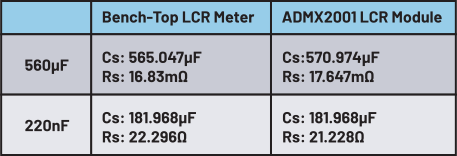
To validate measurement integrity, the customer performed correlation checks between the probe-card-based solution and the original bench-top LCR meter. The results are shown in Figure 6. The comparison showed good agreement in measured capacitance and ESR for representative components under the intended screening conditions. In addition, the embedded solution demonstrated stable behavior across multisite operation, supporting its suitability for production deployment where repeatability and correlation maintenance are essential.
Key Takeaway
This case demonstrates that for automotive capacitor ESR testing, low-impedance sensitivity and throughput constraints are both important. An embedded, probe-card-based LCR approach using the ADMX2001 modules can provide a practical balance of correlation, repeatability, and multisite scalability, compared with a conventional external bench LCR meter configuration.
Conclusion and Future Outlook
As ATE test flows move toward higher parallelism and deeper parametric coverage, embedded LCR capability is increasingly becoming a practical and scalable approach for production environments. Instead of relying on external instruments, placing impedance measurement closer to the DUT helps reduce sensitivity to parasitics and supports repeatable screening while meeting throughput requirements.
This trend also aligns with the growing demand from AI devices that leverage advanced packaging. As more passive components (for example, capacitors) are integrated within the package, impedance-related characterization becomes more important, often under high-site-count and high-pin-count test conditions. As for SiC/GaN and MOSFET testing, there is also a need for higher bias voltage. To maintain the module’s compact size, we are exploring ways to integrate the biasing circuit into the existing ADMX2001.
Looking forward, modular measurement architectures will be an important enabler for next-generation test systems. Replicable LCR blocks allow straightforward scaling from single-site to multisite operation with manageable integration and validation effort, positioning embedded LCR solutions well for future ATE architectures.
Acknowledgment
The author would like to express sincere appreciation to the ADI ISS team for providing the compact, high-precision module that made this work possible. Special thanks also go to AE Slater Campbell for his outstanding technical support and close collaboration, which were instrumental in helping our field team successfully implement this solution in the ATE space.
著者について
Lydia Chen is a field applications engineer at Analog Devices. She holds an M.S. degree in electrical engineering from National Chiao Tung University. She joined ADI in 2019 and primarily supports instrumentation and ATE