要約
Doubler or inverter charge pumps can halve an input voltage with high efficiency. This application note describes how to design 0.5X step-down charge-pump circuits.
Small size and high efficiency (approaching 100%) have made switched-capacitor charge pumps (Q pumps) extremely popular for voltage doubling and inverting in miniature dc-dc applications. Few are aware, however, that most Q pumps can halve an input voltage as well as double or invert it. The increasing use of low-voltage logic makes this divide-by-2 capability very useful for generating the low-voltage supply in new portable-equipment designs. It can, for example, convert a 3.6V RF supply voltage to 1.8V for powering low-voltage logic (Figure 1).
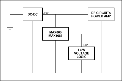
Figure 1. In a typical divide-by-2 application, the charge-pump IC lowers 3.6V to 1.8V for use by low-voltage logic.
Simply reversing the input and output of a voltage doubler makes it into a voltage divider. Implementing this idea with MAX660 or MAX1683 voltage-doubler charge pumps requires only three external capacitors (Figure 2). Both configurations accept input voltages from 3.6V to 10V, but they offer tradeoffs in size and output-current capability. (Note: the MAX1730 regulated step-down charge pump became available after this application note was written. It accepts 2.7V to 5.5V inputs and converts them to either 1.8V or 1.9V at 50mA. Consider this device in lieu of the unregulated, lower-switching-frequency MAX1683. For higher output currents, consider the MAX1680/1681 in lieu of the lower-switching-frequency MAX660. A higher switching frequency is desirable because it allows smaller external capacitors. Unlike the MAX1730, both the MAX660 and MAX1680/1681 are unregulated devices.)
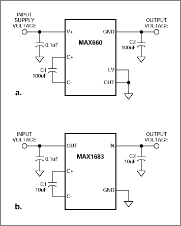
Figure 2. Simple external connections implement VOUT = VIN/2.
For 3.6V inputs, the robust MAX660, which comes in an 8-pin DIP or SO package, delivers 150mA with efficiency greater than 88% and an output-voltage drop of less than 300mV. If a smaller package is essential, the MAX1683 (available in a 5-pin SOT23) offers 50mA capability with a 3.6V input and up to 100mA with inputs above 8V. At 3.6V, its efficiency is 97% at 5mA and 86% at 50mA.
Each device has an internal clock. The MAX660 runs at a nominal 10kHz (with the FC pin open), and the MAX1683 runs at a nominal 35kHz. Each voltage divider's output resistance depends on the internal clock frequency, flying capacitor C1, resistance of the internal switches, and the resistance of the output capacitor C2:

where fOSC is the oscillator frequency, R1-R4 are Rds(ON) values for the four internal switches, and RESR is the equivalent series resistance for the output capacitor C2.
Four graphs illustrate the performance of charge pumps operating in the voltage-divider mode: output resistance vs. input voltage and load current is depicted for the MAX1683 (Figure 3a) and MAX660 (Figure 3b), and efficiency vs. input voltage and load current is depicted for the MAX1683 (Figure 4a) and MAX660 (Figure 4b).
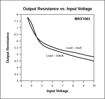
Figure 3a.
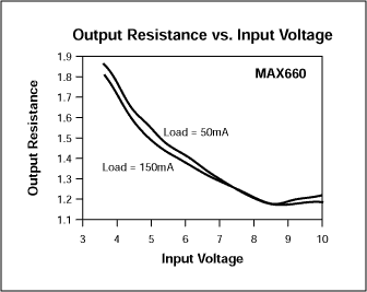
Figure 3b.
Figure 3. Output resistance for a divide-by-2 charge pump decreases with increasing input voltage for the MAX1683 (a) and MAX660 (b).
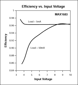
Figure 4a.
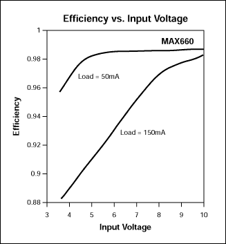
Figure 4b.
Figure 4. Efficiency for a divide-by-2 charge pump varies with input voltage and load current for the MAX1683 (a) and MAX660 (b).


