Adding Autorestart Capability to the MAX16046 EEPROM-Programmable System Manager
要約
The MAX16046 is an EEPROM-configurable system manager that can monitor, sequence, track, and margin multiple system voltages. This design idea will show that by simply adding a small external device to the MAX16046, you can perform a system autorestart following a command from a microcontroller or an external key switch.
The MAX16046 is an EEPROM-configurable system manager that can monitor, sequence, track, and margin multiple system voltages. It integrates an analog-to-digital converter (ADC) for monitoring supply voltages, digital-to-analog converters (DACs) for adjusting supply voltages, and configurable outputs for sequencing and tracking supplies (during power-up and power-down). Nonvolatile EEPROM registers are configurable for storing upper- and lower-voltage limits, setting timing and sequencing requirements, and for storing critical fault data for readback following failures. The internal ADC measures each input and compares the result to one upper, one lower, and one selectable upper or lower limit. A fault signal asserts when a monitored voltage falls outside the set limits; if a monitored voltage is set as critical, all enable outputs are deasserted.
If the latch-on fault mode is selected, the MAX16046 does not reinitiate the power-up sequence until EN is toggled or the active-low Software Enable bit is reset to 0. If the fault behavior is autoretry, the device restarts after a configurable delay.
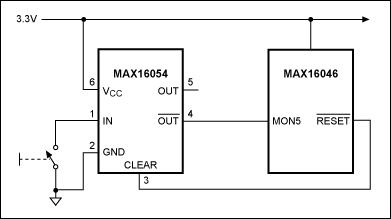
For some applications, such as a main controller unit where reset is not possible, it is possible to perform a system autorestart following a command from a microcontroller or an external key switch. This can be accomplished using a flip-flop and the fault-management scheme of the MAX16046. In Figure 1, the MAX16054, an on/off pushbutton controller with a single debouncer switch and built-in latch, has been used. It accepts a noisy input from a mechanical switch and produces a clean latched digital output after a factory-fixed qualification delay.

Figure 1. The MAX16054 accepts a noisy input from a mechanical switch and produces a clean latched digital output after a factory-fixed qualification delay.
The circuit has been tested on the MAX16046EVKIT. A critical fault on UV has been set on MON5 (Figure 2).
Figure 2. The Setup tab of the MAX16046EVKIT GUI shows that a critical fault on UV is set on MON5.
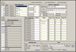
The RESET pin has been configured as active high, and the fault behavior has been selected as autoretry with a delay of 1.6s (Figure 3).
Figure 3. The Details tab of the MAX16046EVKIT GUI shows the RESET pin configured as active high.The fault behavior is selected as autoretry with a delay of 1.6s.
When the key switch is closed:
- The active-low OUT of the MAX16054 asserts low, generating the critical fault condition (Figure 4).
- All the enables are deasserted.
- RESET is asserted high, clearing the fault condition.
- After the 1.6s delay, the system restarts.

Figure 4. The Fault tab of the MAX16046EVKIT GUI shows the MON5 fault condition logged in EEPROM.
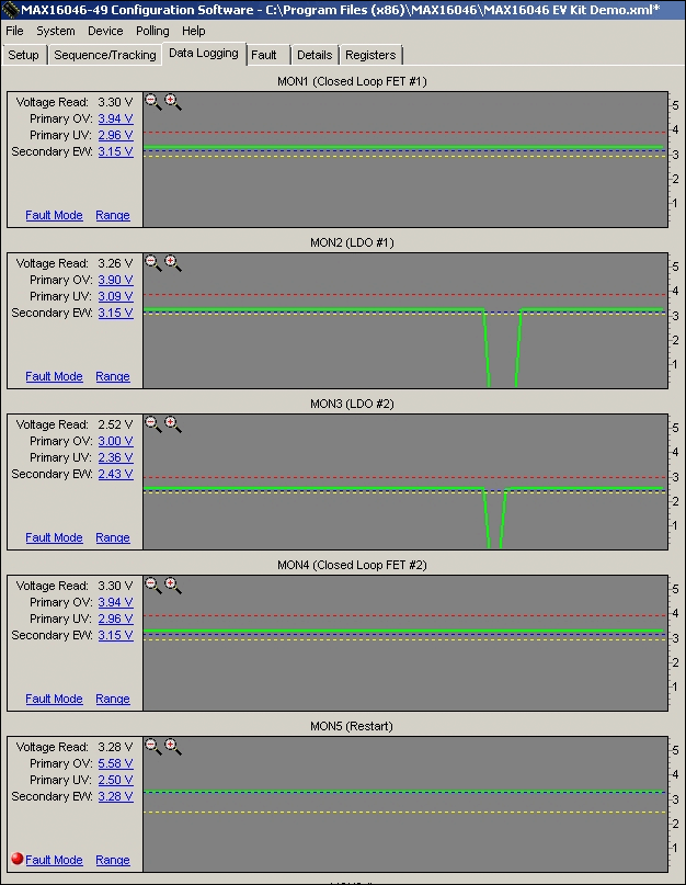
In Figure 5, MON1 and MON4 stay high, because they are measured at the MOSFET input. After each push-button restart, the EEPROM fault flags section of the MAX16046 must be cleared.

Figure 5. The Data Logging tab of MAX16046EVKIT GUI shows the fault detected on MON5 and the voltage restart.
 More detailed image
 More detailed image