MAX17573
Info: : 製造中
searchIcon
cartIcon

MAX17573

内部補償を備えた4.5V~60V、3.5A、高効率、同期整流式降圧DC/DCコンバータ

すべて表示 showmore-icon

MOSFETを内蔵した高効率、高電圧、同期整流式降圧DC/DCコンバータ

Info: : 製造中 tooltip
Info: : 製造中 tooltip

質問する

modal close icon

以下に質問を入力すると、アナログ・デバイセズのナレッジ・ベースからよくある質問の答えを見ることができます。

検索

search button redirect icon

その他のサポート

サポート

アナログ・デバイセズのサポート・ページはアナログ・デバイセズへのあらゆるご質問にお答えするワンストップ・ポータルです。

ADIサポート・ページはこちら
Engineer Zone Icon

ADIコミュニティに問い合わせる。

EngineerZoneコミュニティはこちら

Tool_OpenIcon

よく聞かれる質問(FAQ)

製品モデル 2
1Ku当たりの価格 最低価格:$2.03
特長
  • 外付け部品数および総コストを削減
    • ショットキー不要の同期整流式動作
    • 内部ループ補償
    • 全セラミック・コンデンサ、小型レイアウト
  • DC/DCレギュレータの在庫数を削減
    • 広い入力電圧範囲:4.5V~60V
    • 可変出力電圧範囲:0.9V~VINの90%
    • 外部クロック同期を備えた可変周波数:100kHz~2.2MHz
  • 消費電力を低減
    • ピーク効率:95.4%(VIN = 12V、VOUT = 5V、スイッチング周波数:500kHz)
    • MAX17574とピン・コンパチブル、MAX17574と比較して優れたスイッチング性能により効率を向上
    • PFMおよびDCMモードにより軽負荷効率の向上
    • 補助ブートストラップ電源(EXTVCC)により効率を向上
    • シャットダウン電流:2.8µA
  • 過酷な産業環境で信頼性の高い動作
    • ヒカップ・モード過負荷保護内蔵
    • 出力電圧監視内蔵(RESET
    • 設定可能なEN/UVLO閾値
    • 出力電圧へのプリバイアスでの可変かつ単調な起動
    • 過熱保護
製品概要
show more Icon

MAX17573はMOSFETを内蔵した高効率、高電圧、同期整流式降圧DC/DCコンバータで、4.5V~60Vの入力で動作します。このコンバータは最大3.5Aの電流を供給可能です。出力電圧は0.9V~VINの90%の範囲で設定可能です。-40℃~+125℃でのフィードバック電圧の安定化精度は±0.9%です。

このデバイスは、ピーク電流モード制御アーキテクチャを採用しています。内部トランスコンダクタンス・エラーアンプは内部ノードで積算誤差電圧を生成し、それによりPWMコンパレータ、ハイサイド電流検出アンプ、およびスロープ補償発生器を使用してデューティ・サイクルが設定されます。クロックの各立上りエッジでハイサイドMOSFETがオンになり、適切なデューティ・サイクルまたは最大デューティ・サイクルに到達するか、またはピーク電流制限が検出されるまでオンのままになります。ハイサイドMOSFETのオン時間の間、インダクタ電流は増大します。スイッチング・サイクルの後半で、ハイサイドMOSFETはオフになり、ローサイドMOSFETはオンになります。インダクタ電流の減少とともにインダクタは蓄積されたエネルギーを解放して、出力に電流を供給します。

このデバイスは、パルス幅変調(PWM)、パルス周波数変調(PFM)、または断続コンダクション・モード(DCM)制御方式のいずれかで動作可能です。設定可能なソフトスタート機能により入力突入電流を低減できます。また、このデバイスはイネーブル/入力低電圧ロックアウト・ピン(EN/UVLO)も備えているため、所望の入力電圧レベルでデバイスをオンにすることができます。出力電圧の正常な安定化を達成すると、オープンドレインのRESETピンは遅延を備えたパワー・グッド信号をシステムに提供します。

アプリケーション

  • ファクトリ・オートメーション
  • アフターマーケット車載製品
  • 汎用ポイント・オブ・ロード

質問する

modal close icon

以下に質問を入力すると、アナログ・デバイセズのナレッジ・ベースからよくある質問の答えを見ることができます。

検索

search button redirect icon

その他のサポート

サポート

アナログ・デバイセズのサポート・ページはアナログ・デバイセズへのあらゆるご質問にお答えするワンストップ・ポータルです。

ADIサポート・ページはこちら
Engineer Zone Icon

ADIコミュニティに問い合わせる。

EngineerZoneコミュニティはこちら

Tool_OpenIcon

よく聞かれる質問(FAQ)

製品モデル 2
1Ku当たりの価格 最低価格:$2.03

利用上の注意

close icon

アナログ・デバイセズ社は、提供する情報が正確で信頼できるものであることを期していますが、その情報の利用に関して、あるいはその利用によって生じる第三者の特許やその他の権利の侵害に関して一切の責任を負いません。また、アナログ・デバイセズ社の特許または特許の権利の使用を明示的または暗示的に許諾するものでもありません。仕様は予告なしに変更する場合があります。本紙記載の商標および登録商標は、各社の所有に属します。


本データシートの英語以外の言語への翻訳はユーザの便宜のために提供されるものであり、リビジョンが古い場合があります。最新の内容については、必ず最新の英語版をご参照ください。

なお、日本語版のデータシートは基本的に「Rev.0」(リビジョン0)で作成されています。そのため、英語版が後に改訂され、複数製品のデータシートがひとつに統一された場合、同じ「Rev.0」の日本語版のデータシートが異なる製品のデータシートとして表示されることがあります。たとえば、「ADM3307E」の場合、日本語データシートをクリックすると「ADM3311E」が表示されます。これは、英語版のデータシートが複数の製品で共有できるように1本化され、「ADM3307E/ADM3310E/ADM3311E/ADM3312E/ADM3315E」(Rev.G)と改訂されたからで、決して誤ってリンクが張られているわけではありません。和文化されたデータシートを少しでも有効に活用していただくためにこのような方法をとっておりますので、ご了解ください。

ドキュメント

アナログ・デバイセズは、最高レベルの品質と信頼性を満たす製品を供給することを常に最重要視しています。これを実現するため、製品、プロセス設計、更には製造プロセスに対しあらゆる観点から品質と信頼性のチェックを行っています。アナログ・デバイセズでは出荷製品に対する「ゼロ・ディフェクト」を常に目指しています。詳細については、アナログ・デバイセズの品質および信頼性プログラム、認証のページを参照してください。
製品モデル ピン/パッケージ図 資料 CADシンボル、フットプリント、および3Dモデル
MAX17573ATG+
  • HTML
  • HTML
MAX17573ATG+T
  • HTML
  • HTML

ソフトウェアおよび製品のエコシステム

評価用キット 3

MAX17573EVKITA

Evaluation Kit for the MAX17573 in 5V and 3.3V Output- Voltage Applications

zoom

MAX17573EVKITA

Evaluation Kit for the MAX17573 in 5V and 3.3V Output- Voltage Applications

Evaluation Kit for the MAX17573 in 5V and 3.3V Output- Voltage Applications

機能と利点

  • Operates over a Wide Input Range
    • MAX17573EVKITA#: VOUT1 = 3.3V, IOUT1 = 3.5A, VIN1 Range = 4.5V to 60V
    • MAX17573EVKITB#: VOUT2 = 5V, IOUT2 = 3.5A, VIN2 Range = 6.5V to 60V
  • Enable/UVLO Input, Resistor-Programmable UVLO Threshold
  • Selectable PWM, PFM, and DCM Modes of Operation
  • Adjustable Soft-Start Time
  • Active-Low RESET Output with a Pullup Resistor to an External Supply
  • External Clock Synchronization
  • Overcurrent and Overtemperature Protection
  • Proven PCB Layout
  • Fully Assembled and Tested
  • Complies with CISPR 32 (EN55032) Class B Conducted and Radiated Emissions

製品の詳細

The MAX17573 evaluation kit (EV kit) provides proven 3.3V and 5V designs to evaluate the MAX17573 high-efficiency, wide input voltage Himalaya synchronous DC-DC converter. The 3.3V application circuit delivers load current up to 3.5A from a wide 4.5V to 60V input supply and operates at a 500kHz switching frequency. The 5V application circuit delivers load current up to 3.5A from a wide 6.5V to 60V input supply and operates at a 500kHz switching frequency.

Each application circuit on the EV kit features programmable enable and input Undervoltage Lockout (UVLO), soft-start, open-drain active-low RESET signal, and external clock synchronization. The EV kit’s layout is optimized for conducted and radiated EMI and thermal performance. For more details, refer to the Product Highlights section in the MAX17573 IC data sheet.

MAX17573EVKITB

Evaluation Kit for the MAX17573 in 5V and 3.3V Output- Voltage Applications

zoom

MAX17573EVKITB

Evaluation Kit for the MAX17573 in 5V and 3.3V Output- Voltage Applications

Evaluation Kit for the MAX17573 in 5V and 3.3V Output- Voltage Applications

機能と利点

  • Operates over a Wide Input Range
    • MAX17573EVKITA#: VOUT1 = 3.3V, IOUT1 = 3.5A, VIN1 Range = 4.5V to 60V
    • MAX17573EVKITB#: VOUT2 = 5V, IOUT2 = 3.5A, VIN2 Range = 6.5V to 60V
  • Enable/UVLO Input, Resistor-Programmable UVLO Threshold
  • Selectable PWM, PFM, and DCM Modes of Operation
  • Adjustable Soft-Start Time
  • Active-Low RESET Output with a Pullup Resistor to an External Supply
  • External Clock Synchronization
  • Overcurrent and Overtemperature Protection
  • Proven PCB Layout
  • Fully Assembled and Tested
  • Complies with CISPR 32 (EN55032) Class B Conducted and Radiated Emissions

製品の詳細

The MAX17573 evaluation kit (EV kit) provides proven 3.3V and 5V designs to evaluate the MAX17573 high-efficiency, wide input voltage Himalaya synchronous DC-DC converter. The 3.3V application circuit delivers load current up to 3.5A from a wide 4.5V to 60V input supply and operates at a 500kHz switching frequency. The 5V application circuit delivers load current up to 3.5A from a wide 6.5V to 60V input supply and operates at a 500kHz switching frequency.

Each application circuit on the EV kit features programmable enable and input Undervoltage Lockout (UVLO), soft-start, open-drain active-low RESET signal, and external clock synchronization. The EV kit’s layout is optimized for conducted and radiated EMI and thermal performance. For more details, refer to the Product Highlights section in the MAX17573 IC data sheet.

reference details image

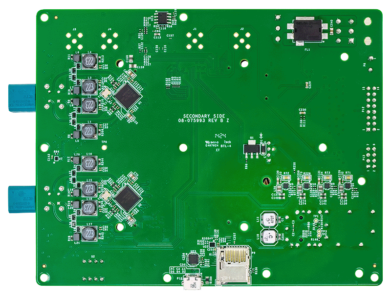
AD-GMSL2ETH-SL

FPGA-based 8x GMSL to 10 Gb Ethernet Adapter

zoom

AD-GMSL2ETH-SL

FPGA-based 8x GMSL to 10 Gb Ethernet Adapter

FPGA-based 8x GMSL to 10 Gb Ethernet Adapter

機能と利点

  • Edge compute platform for machine vision and real-time sensor fusion for autonomous robots and vehicles applications
  • 8 x GMSL2 camera interfaces with up to 6 Gbps/channel
  • 10 Gbps SFP+ Ethernet interface
  • IEEE 1588 Precision Time Protocol for synchronization with host systems and other edge devices
  • Advanced embedded processing capabilities
  • ROS2 compliant
  • Advanced camera triggering functions and control features
  • Open-source software stack and FPGA design to enable custom applications development

製品の詳細

The AD-GMSL2ETH-SL is an edge compute platform enabling low-latency data transfer from eight Gigabit Multimedia Serial Link™ (GMSL) interfaces on to a 10 Gb Ethernet link. The target applications include autonomous robots and vehicles where machine vision and real-time sensor fusion is critical.

The system includes two MAX96724 Quad Tunneling GMSL2/1 to CSI-2 Deserializers, enabling connectivity to eight GMSL cameras. The video data from the cameras is transferred from the MAX96724 deserializers via MIPI CSI2 interfaces to an AMD KV26 System on Module which implements the logic to aggregate the video data from all the GMSL cameras into a 10 Gb Ethernet link, so that it can be sent to a central processing unit.

The IEEE 1588 Precision Time Protocol (PTP) with hardware timestamping is supported, enabling accurate synchronization with host systems and other edge devices. The AD9545 Quad Input, 10-Output, Dual DPLL/IEEE 1588, 1 pps Synchronizer and Jitter Cleaner is used to generate the required clocks for the 10 Gb Ethernet interface and the PTP logic.

A software networking stack can be used to realize the communication over the 10 Gb Ethernet link. Since the system runs Linux tools like gstreamer can be used to send the video data to a host and remote connection into the system is possible via ssh. The software network stack has limitations in terms of the maximum achievable transfer rate, and for this reason there is also the option to have an FPGA accelerated UDP or TCP implementation with Real Time Transfer (RTP) protocol for data packetization, which can get up to the maximum achievable data rate on the 10 Gb ethernet interface.

Accurate camera triggering control is achieved through dedicated FPGA logic, with configurable frequency and phase as well as selecting the trigger source between the internal logic and external signals.

Sixteen (16) general purpose I/O pins are available with software configurable functionality, operating at 3.3 V voltage level. A RS232 dedicated interface can be used to connect UART peripherals such as GNSS devices.

The design is accompanied by an open-source software stack and FPGA design, and reference applications, enabling custom software development to start from a proven implementation.

APPLICATIONS

  • Autonomous robots and vehicles

ツールおよびシミュレーション 1

最近表示した製品