Scaling the RF Digitizer Subsystem—Part 1: How SOMs Accelerate Integration and Deployment

Scaling the RF Digitizer Subsystem—Part 1: How SOMs Accelerate Integration and Deployment
Aug 31 2026
Key Takeaways
|
Abstract
This article presents Analog Devices’ software-defined radio ecosystem and system-on-module portfolio, designed to accelerate RF system development from concept to deployment. Leveraging zero-IF architecture and prevalidated hardware/software stacks, these solutions enable compact, scalable designs for applications such as tactical radios, drones, unmanned aerial vehicles, satellite communication, weather sensing, phased array radar, and more. Features such as multichip sync and modular expansion simplify building advanced architectures like massive MIMO and beamforming with reduced cost and complexity.
Introduction
With wireless intelligence expanding at the edge, traditional fixed-function RF hardware can’t keep pace with the need for flexible, multiband, software-driven systems. Software-defined radio (SDR) platforms now play a leading role, enabling rapid adaptation to new standards, efficient spectrum use, and operation within strict size, weight, and power (SWaP) limits.
This article introduces ADI’s SDR ecosystem, supported by our system-on-module (SOM) portfolio designed for applications requiring <1GHz instantaneous bandwidth (iBW). These SOMs integrate validated RF, digital, power, and synchronization subsystems—reducing design complexity and accelerating the path from prototype to deployable product. A case study within the CN0566 phased array platform demonstrates how ADI’s system solutions compress development timelines for radar, communications, and sensing systems. With built-in multichip sync (MCS) delivering subnanosecond alignment, these platforms make advanced architectures such as massive MIMO and beamforming arrays far more accessible when paired with clocking solutions like the AD-SYNCHRONA14-EBZ. Together, this ecosystem of platform solutions provides a fast, reliable path for building and deploying next-generation RF products with greater speed, confidence, and scalability.
Zero-IF Architecture Advantages and this SOM Portfolio
For applications requiring iBW <1GHz coverage, a zero-intermediate frequency (IF) architecture (also called direct conversion to baseband, complex baseband, or homodyne) provides the perfect blend of performance, power efficiency, and integration.1 This architecture directly downconverts the RF signal to an I/Q baseband near 0Hz, eliminating the need for bulky and expensive IF filters, amplifiers, and additional gain stages. See Figure 1.
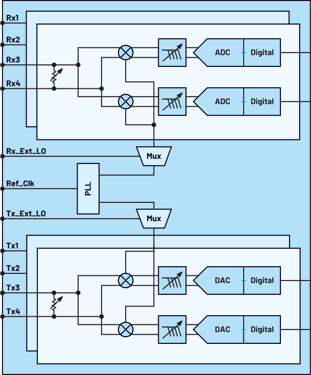
This modern design has worked well in mitigating zero-IF architecture difficulties such as DC offset/LO leakage, quadrature (I/Q) mismatch (gain/phase errors/image issues), noise figure, linearity, and made it more efficient by built-in RF and baseband (BB) calibration routines, digital DC correction loss, image rejection compensation algorithms, and transceiver startup calibrations. This is why zero-IF designs can result in a 50% smaller PCB footprint at one-third the cost of traditional architectures.2
Zero-IF’s advantages are particularly pronounced in:
-
Multiband radios and carrier aggregation: A single hardware platform can be reconfigured via software to support multiple frequency bands. This flexibility simplifies design complexity, reduces hardware variations, and accelerates time-to-market.
-
SWaP-constrained devices: By eliminating bulky IF components, zero-IF significantly reduces board size, power consumption, and overall cost—ideal for applications where SWaP are critical.
-
Cognitive radios: With most signal processing handled in the digital domain, zero-IF enables real-time adaptability for dynamic spectrum environments, paving the way for next-generation intelligent communication systems.
Table 1 details the zero-IF-based SOM portfolio, providing a snapshot of their capabilities and target applications.
| SOM Module | Tuning Range | Bandwidth | Interfaces | FPGA Resources (Logic/DSP) | Example Applications | Bandwidth Enables |
| Pluto SOM (AD9363 + Zynq™-7010) | 325MHz to 3.8GHz | 200kHz to 20MHz | LVDS, SPI, GPIO | ~28k/80 | IoT gateways, smart agriculture, remote monitoring, low SWaP drone telemetry | Narrow-band telemetry protocols, FM radio basic unmanned aerial vehicle (UAV) telemetry, and control |
| ADRV9364 SOM (ADRV9364 + Zynq-7020) | 70MHz to 6GHz | 200kHz to 56MHz | LVDS, SPI, GPIO | ~85k/220 | Single-channel radios, smart grid, tactical radios (low SWaP), UAV links, telemetry | Single-channel radios and telemetry, mid-rate drone comms, narrow-band tactical links |
| ADRV9361 SOM (ADRV9361 + Zynq-7035) | 70MHz to 6GHz | 200kHz to 56MHz | LVDS, SPI, GPIO | ~277k/900 | LTE/5G small cells, Wi-Fi backhaul, multichannel spectrum analyzers, tactical comms, drone swarms | Multichannel LTE/Wi-Fi, spectrum monitoring, multilink UAV command and control |
| Jupiter SOM (ADRV9002 + Zynq UltraScale+™ ZU3EG) | 30MHz to 6GHz | 12kHz to 40MHz | LVDS, SPI, GPIO | ~154k/360 | Secure tactical radios, frequency-hopping radios, UAV C2, resilient mesh, electronic support (ES) | Secure/narrow-band waveforms, frequency-agile tactical links, resilient comms (C2), spectrum-aware radios |
| ADRV9009 SOM (ADRV9009 + Zynq UltraScale+ ZU11EG) | 75MHz to 6GHz | Rx: up to 200MHz, Tx: up to 450MHz | 8-lane JESD204B/C | ~504k/1,968 | Massive MIMO 5G, phased array radar, electronic measures, countermeasures, satcom, wideband spectrum monitoring | Wideband radar/EW, multicarrier 5G, wideband satcom, high-fidelity EW and jamming/recon (lawful, controlled environments) |
Accelerating System Prototyping with Prevalidated Hardware and Software
What’s Fabricated
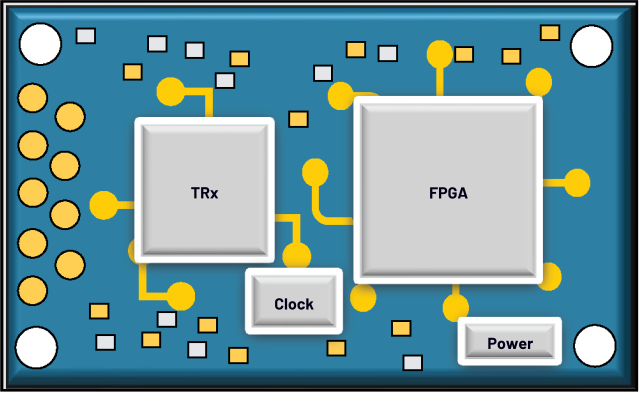
Our SOMs arrive as prevalidated hardware platforms (Figure 2) designed to eliminate RF design risks and accelerate development. The RF front-end integrates low-jitter phase-locked loops (PLLs), sequenced and isolated power rails, and layouts that follow best practices in shielding and grounding to deliver low-error vector magnitude (EVM) and high signal integrity. High-speed digital interfaces such as JESD204B/C and low-voltage differential signaling (LVDS) are evaluated for multi-Gbps throughput with deterministic latency, with challenges like signal integrity and length matching already resolved. More to this, the modules can be further optimized in increasing power efficiency and enhancing the system.3 For multiradio systems, built-in MCS and device clock distribution enable sub-nanosecond alignment, ensuring phase coherence essential for phased array radar, massive MIMO, and other synchronized RF applications.
Software Enablement: From First Power-On to Standalone Deployment
ADI provides the reference software packages for each supported tool chain.
-
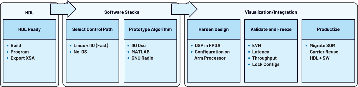
FPGA hardware description language (HDL): ADI support includes FPGA reference designs built-in Vivado that have been synthesized, simulated, and validated with JESD/LVDS datapaths, direct memory access (DMA) engines, and synchronization logic.
-
Software stacks:
-
Visualization/integration: Both the development software methods of Linux and the no-OS driver are complemented by visualization and modeling tools, such as IIO Oscilloscope for signal inspection and MATLAB®/GNU radio for algorithm development. Figure 3 shows the flowgraph for software development.4
Bringing Up the SOM: A Step-by-Step Process
-
Step 1: FPGA bring-up
This is to get the fabric running with known good JESD/LVDS + DMA + sync so software can control it.-
Get the reference SOM project by cloning HDL.
-
Next, generate and build the Build project (Vivado Tcl scripts → synthesize/implement), parameters of JESD, clock rates, and datapath width are customizable based on requirements.
-
Further program the FPGA, generate the bit stream, and export the XSA (used by Linux/no-OS builds).
-
-
Step 2: configure and control the software paths
-
Linux + IIO Path (quick iteration and richest tooling)
-
Boot ADI Linux on the SOM. Software overview can be referred here.
-
Verify IIO devices, for example, iio_info (via libiio). This helps with seeing devices for transceivers.
-
To query an attribute, use iio_attr.
-
Further use IIO Osc, MATLAB/Simulink, or GNU Radio via libiio. Best for development speed, scripting, and remote control.5
-
-
This approach is useful when instrumentation, logging, networking, scripting, remote control, and easy integration with MATLAB or GNU radio are required. While the resulting latency is acceptable, the lowest latency is achieved by moving computation onto the FPGA (see embed for low latency in Step 4).6
-
Bare-metal (no-OS) path (deterministic)
-
Clone no-OS and choose the project, then select the device/platform.
-
Configure in main.c to set the LO, bandwidth, sampling rates, gains, GPIO, profile…
-
Build and load with Vitis/SDK using the exported XSA from HDL.
-
Build with this when you need tight control loops, small footprints, and predictable execution without Linux.
-
Step 3: application-layer prototyping (PC in the loop)
-
IIO Oscilloscope: first signal checks (LO, gain, BW, levels, FFT).
-
MATLAB/Simulink: develop filters, synchronizers, beam-formers; stream live data via libiio; validate with the real RF chain; autogenerate HDL (HDL Coder) and C (Embedded Coder) when ready.7
-
GNU Radio: quickly wire up flowgraphs (modulation, coding, packetization, link tests) with IIO source/sink blocks for live I/O.
-
PC in the loop is ideal for rapid iteration but introduces network/USB buffering. For μs class latency, embed the algorithm in FPGA fabric, the following section discusses it in more detail.
-
Step 4: embed for standalone, low latency operation
-
Start with converting algorithm to HDL and this can be done by either using HDL Coder (from Simulink) or writing VHDL/Verilog by hand.
-
Target AXI4 Stream for sample data and AXI4 Lite for control/status.
-
-
Next, integrate into ADI HDL platform (Vivado).
-
Drop the IP in the block design and connect to ADI DMA for streams and to control interconnect for registers.
-
-
Program the SOM to generate the bitstream and export the XSA to the Linux/no-OS build.
-
Expose controls and run headless.
-
For Linux, add IIO attributes or a simple char device for the IP registers and control via IIO Osc, Python (pylibiio), or your app with libiio.
-
For no-OS extend main.c to write/read the IP registers and perform runtime control.
-
-
This will result in pushing the critical DSP (filters/FFT/beamforming/DPD/etc.) to run in fabric at line rate → microsecond level latency. The Arm® Processor (Linux or bare metal) just sets parameters and orchestrates.
These configurations prepare the SOM/digitizer module for the next phase of system design.
SOM/Digitizer to Subsystem Design: CN0566 a Phased Array Radar Case Study
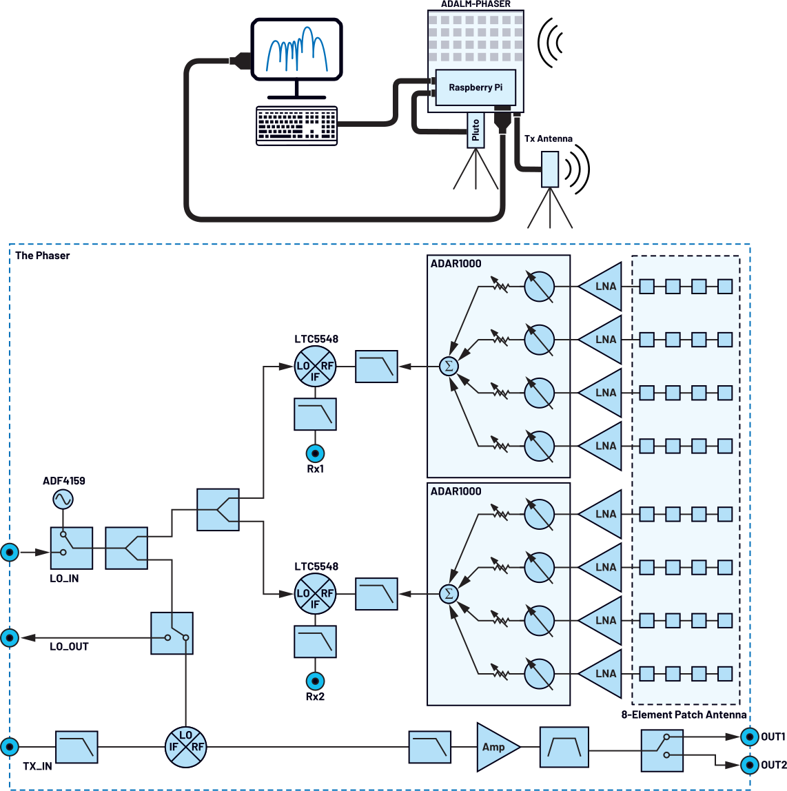
ADI’s ADALM-PHASER (part number CN0566) demonstrates how a Pluto SOM can extend beyond its native RF range to prototype an X-band (10GHz to 10.5GHz) phased array radar. The front end downconverts X-band signals to a 2.2GHz IF that the Pluto SOM digitizes, while an ADAR1000 beamformer provides per-element 360° phase control (2.8° resolution) and 31dB amplitude control (0.5dB steps) for agile beam steering and gain shaping.
Beamformer control is handled via SPI from a host (PC or Raspberry Pi), and I/Q data streams from a Pluto SOM into standard SDR tool chains (IIO Osc, GNU Radio, MATLAB).
The ADALM-PHASER provides a low-cost, hands-on phased array front end to evaluate beam steering, frequency modulated continuous wave (FMCW) radar, direction finding, and basic array algorithms without building a custom X-band RF chain. This architecture, as shown in Figure 4, highlights how an off-the-shelf SOM can enable rapid phased array prototyping—beamforming, calibration, and visualization—without building a full RF chain from scratch.
Scaling Up the System
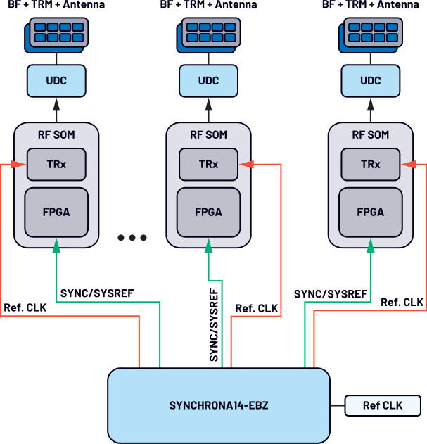
Scaling an SDR prototype from a single SOM into a multichannel or multi-module system requires consistent timing, low-jitter clocking, and predictable data transport. ADI SOMs are designed for this progression, supporting MCS, deterministic JESD204B/C operation, and high-speed expansion interfaces such as FMC+, PCIe, and Gigabit Ethernet. Together, these features allow multiple SOMs to work as a coherent, phase-aligned platform suitable for applications ranging from phased array radar to multiband satcom terminals.
A clock-distribution solution such as the AD-SYNCHRONA14-EBZ helps deliver these signals with low skew and low jitter, ensuring that every module samples at the same temporal reference.
While not required in all designs, its use simplifies larger, timing-sensitive arrays by providing aligned clock and SYSREF outputs with picosecond-level accuracy.
A typical bring-up process involves verifying reference clock integrity, confirming SYSREF alignment, and checking that JESD lanes report code group synchronization (CGS), frame alignment, and stable deterministic latency. A simple coherence test—injecting a single continuous wave (CW) tone into all channels and comparing their resulting phase—quickly validates system alignment.
From there, system expansion is straightforward. More SOMs, ADC/DAC front ends, or FPGA accelerators can be added through FMC+ or PCIe without redesigning the RF section. Since each SOM supports its own calibrated RF signal chain and timing alignment, scaling the system effectively becomes a matter of connecting additional modules while preserving shared clock and trigger distribution. See Figure 5 for reference.
By combining clean clocking, deterministic digital interfaces, and integrated calibration flows, ADI SOMs enable system designers to scale rapidly without touching the RF front end. Whether the goal is to prototype a compact UAV radio, expand to a 16-channel phased array demonstrator, or build a multiband sensing system, the underlying approach remains consistent—shared timing, synchronized sampling, and modular expansion.
Conclusion
ADI’s zero-IF-based SOM portfolio enables developers to move from concept to working prototypes with validated hardware, robust software stacks, and seamless integration into higher-level systems. Whether building IoT gateways, tactical radios, or phased array radars, engineers can scale designs by reusing the same SOM infrastructure—accelerating innovation while reducing cost and complexity. Combining compact hardware, synchronized multichip support, and rich software enablement empowers teams to focus on algorithms, applications, and mission success, leaving the complexity of RF design already solved.
Stay tuned for Part 2, which dives into how our mixed-signal front-end (MxFE®) series for next-generation advanced radar, satcom, EW application delivers direct RF sampling solutions that are highly integrated, ruggedized, scalable, and frequency-independent. It will also explore how ADI is enabling scalable antenna arrays and delivering a path toward end-to-end, off-the-shelf phased array system solutions.
References
1Dave Frizelle and Frank Kearney. “Complex RF Mixers, Zero-IF Architecture, and Advanced Algorithms: The Black Magic in Next-Generation SDR Transceivers.” Analog Dialogue, Vol. 51, February 2017.
2Brad Brannon. “Where Zero-IF Wins: 50% Smaller PCB Footprint at 1/3 the Cost.” Analog Dialogue, Vol. 50, September 2016.
3Chance Fletcher and Florin Hurgoi. “How to Increase Power Efficiency in Software-Defined Radios.” Analog Devices, Inc., July 2025.
4Di Pu, Andrei Cozma, and Tom Hill. “Four Quick Steps to Production: Using Model-Based Design for Software-Defined Radio (Part 1) The Analog Devices/Xilinx SDR Rapid Prototyping Platform: Its Capabilities, Benefits, and Tools.” Analog Dialogue, Vol. 49, September 2015.
5Mike Donovan, Andrei Cozma, and Di Pu. “Four Quick Steps to Production: Using Model-Based Design for Software-Defined Radio (Part 2): Mode S Detection and Decoding Using MATLAB and Simulink.” Analog Dialogue, Vol. 49, October 2015.
6Di Pu and Andrei Cozma. “Four Quick Steps to Production: Using Model-Based Design for Software-Defined Radio Part 3—Mode S Signals Decoding Algorithm Validation Using Hardware in the Loop.” Analog Dialogue, Vol. 49, November 2015.
7Mike Donovan, Andrei Cozma, and Di Pu. “Four Quick Steps to Production: Using Model-Based Design for Software-Defined Radio (Part 4) Rapid Prototyping Using the Zynq SDR Kit and Simulink Code Generation Workflow.” Analog Dialogue, Vol. 49, December 2015.
About the Authors
Siddharth S. Shah is a senior system applications engineer at Analog Devices, based in Bengaluru, India, where he develops system-level application solutions for aerospace and defense. He joined ADI in 2022. Previously, he
Related to this Article
Products
RECOMMENDED FOR NEW DESIGNS
Integrated Dual RF Tx, Rx, and Observation Rx
RECOMMENDED FOR NEW DESIGNS
RF Agile Transceiver
RECOMMENDED FOR NEW DESIGNS
Dual Narrow-Band and Wideband RF Transceiver
Dual ADRV9009 FMC Compatible Prototyping Platform
Phased Array (Phaser) Development Platform
RF System on Module using the ADRV9009 Wideband Transceiver
SDR 1x1 System-On-Module
Software-Defined Radio Active Learning Module
Multichannel System Clocking Device
Direct Modulation/Fast Waveform Generating, 13 GHz, Fractional-...
2GHz to 14GHz Microwave Mixer with Wideband DC–6GHz IF
8 GHz to 16 GHz, 4-Channel, X Band and Ku Band Beamformer