MAX3521
DOCSIS 3.0 Upstream Amplifier
Show MoreIndustry's Highest Performance Upstream Amplifier for DOCSIS 3.0 advanced Applications
Not the part you were looking for?
Ask a Question
Submit your question below and we will return the best answer from ADI’s knowledge database:
Other places you can find help
Support
Analog Devices Support Portal is a one-stop shop to answer all your ADI questions.
Visit the ADI Support PageFeatures
- +5V Supply Voltage
- Ultra-Low 25mW Dissipation in Transmit-Disable Mode
- 63dB Gain-Control Range in 1dB Steps
- -65dBc Harmonic Distortion at 67dBmV Output
- Small 5mm x 5mm TQFN Package
- Low Burst On/Off Transient
- 275MHz, 3dB Bandwidth
- Multiple Power Modes for Optimal Battery Life
The MAX3521 is an integrated CATV upstream amplifier IC designed to exceed the DOCSIS 3.0 requirements. It provides a maximum output power level 3dB higher than the DOCSIS 3.0 specification for all modulation standards and channel configurations. The amplifier covers an 5MHz to 85MHz input frequency range (275MHz, 3dB bandwidth). It is capable of transmitting four QPSK modulated carriers, each at +61dBmV, simultaneously within this range. The gain is controlled in 1dB steps over a 63dB range using an SPI 3-wire interface.
The device operates from a single +5V supply. Four power codes are provided to allow maximum supply current to be reduced as determined by distortion requirements. In addition, for each power code, supply current is automatically reduced as gain is reduced while maintaining distortion performance. The supply current drops to 5mA between bursts to minimize power dissipation in transmit-disable mode. Control signal logic levels are 3.3V CMOS.
The MAX3521 is the most recent addition to Maxim’s pin-compatible cable upstream amplifier family, which includes the MAX3518. The MAX3521 is available in a 20-pin TQFN package and operates over the extended industrial temperature range (-40°C to +85°C).
Applications
- DOCSIS 3.0 Plus Cable Modems and Gateways
- Set-Top Boxes
- VOIP Modems
Ask a Question
Submit your question below and we will return the best answer from ADI’s knowledge database:
Other places you can find help
Support
Analog Devices Support Portal is a one-stop shop to answer all your ADI questions.
Visit the ADI Support Page{{modalTitle}}
{{modalDescription}}
{{dropdownTitle}}
- {{defaultSelectedText}} {{#each projectNames}}
- {{name}} {{/each}} {{#if newProjectText}}
- {{newProjectText}} {{/if}}
{{newProjectTitle}}
{{projectNameErrorText}}
Documentation
ADI has always placed the highest emphasis on delivering products that meet the maximum levels of quality and reliability. We achieve this by incorporating quality and reliability checks in every scope of product and process design, and in the manufacturing process as well. "Zero defects" for shipped products is always our goal. View our quality and reliability program and certifications for more information.
Part Model | Pin/Package Drawing | Documentation | CAD Symbols, Footprints, and 3D Models |
---|---|---|---|
MAX3521ETP+ | 20-LFCSP-5X5X0.75 |
|
|
MAX3521ETP+T | 20-LFCSP-5X5X0.75 |
|
- MAX3521ETP+
- Pin/Package Drawing
- 20-LFCSP-5X5X0.75
- Documentation
- HTML Material Declaration
- HTML Reliablity Data
- CAD Symbols, Footprints, and 3D Models
- Ultra Librarian
- SamacSys
- MAX3521ETP+T
- Pin/Package Drawing
- 20-LFCSP-5X5X0.75
- Documentation
- HTML Material Declaration
- HTML Reliablity Data
- CAD Symbols, Footprints, and 3D Models
- Ultra Librarian
- SamacSys
Filter by Model
Part Models
Product Lifecycle
PCN
Aug 14, 2023
- 2275A
WAFER FAB
MAX3521ETP+
PRODUCTION
MAX3521ETP+T
PRODUCTION
Filter by Model
Part Models
Product Lifecycle
PCN
Aug 14, 2023
- 2275A
WAFER FAB
Software & Part Ecosystem
Evaluation Kits 1
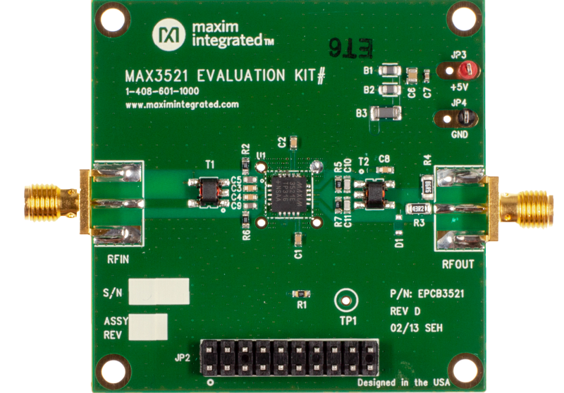
MAX3521EVKIT
Evaluation Kit for the MAX3521
Product Detail
The MAX3521 evaluation kit (EV kit) simplifies the testing and evaluation of the MAX3521 DOCSIS 3.0 upstream amplifier. The EV kit is fully assembled and tested at the factory. Standard 50Ω SMA connectors are included on the EV kit for the inputs and outputs to allow quick and easy evaluation on the test bench.
This document provides a list of equipment required to evaluate the device, a straightforward test procedure to verify functionality, a description of the EV kit circuit, the circuit schematic, a list of components for the EV kit, and artwork for each layer of the PCB.
Applications
- DOCSIS 3.0 Plus Cable Modems and Gateways
- Set-Top Boxes
- VOIP Modems
Resources