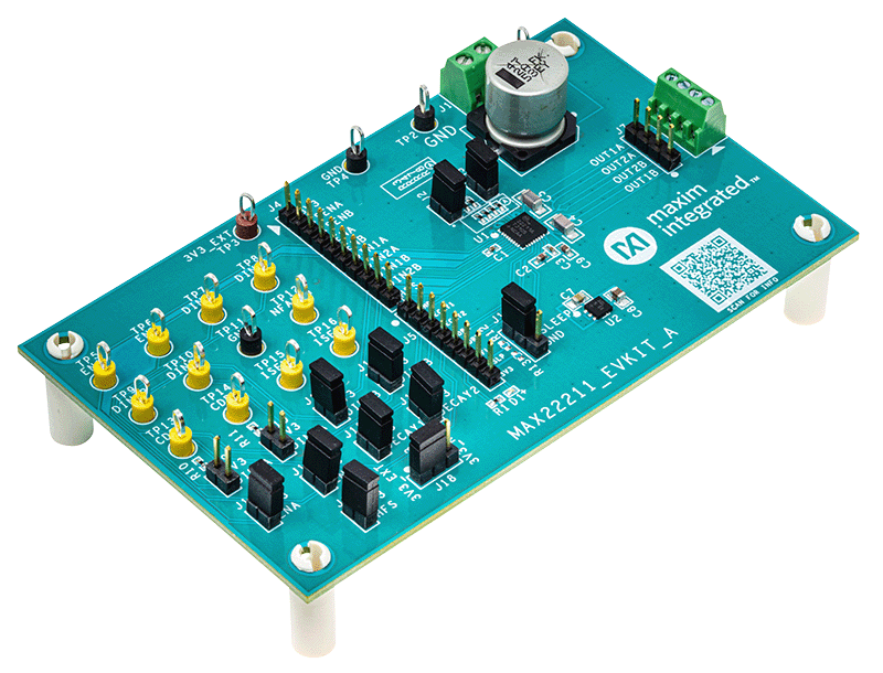
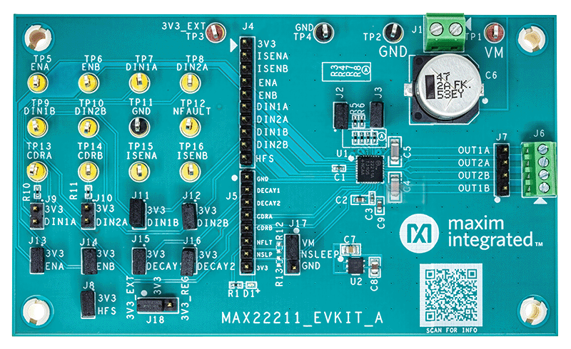
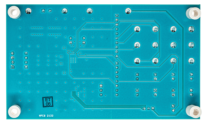
MAX22211
RECOMMENDED FOR NEW DESIGNS36V, 3.8A Two H-Bridge for Dual Brushed or Single Stepper Motor Drive
- Part Models
- 4
- 1ku List Price
- Starting From $1.78
Overview
- Two H-Bridges with +36V Maximum Operating Voltage
- Total RON (High-Side + Low-Side): 250mΩ Typical (TA = 25°C)
- Current Ratings per H-Bridge (Typical at TA = 25°C)
- ITRIP_MAX = 3.8A (Maximum Current Setting for Internal Current Drive Regulation)
- IRMS = 2ARMS (Recommended Maximum RMS Current per Full Bridge)
- Integrated Current Drive Regulation
- ICS Eliminates Bulky External Resistors and Improves Efficiency
- Current Drive Regulation Monitor Output Pins (CDRA, CDRB)
- Four Decay Modes Supported (Slow Decay, Fast Decay, and two Mixed Decays)
- Half Full Scale (HFS) Pin to Improve Current Control Accuracy in the Low Current Range
- Current Sense Output (Current Monitor)
- Fault Indicator Pin (FAULT)
- Low-Power Mode (Sleep Mode)
- Protections
- OCP for Each Individual Channel
- UVLO
- TSD TJ = 165°C
- TQFN32 5mm x 5mm Package and TSSOP28 4.4mm x 9.7mm Package
The MAX22211 is a dual 36V, 3.8AMAX H-bridge. It can be used to drive two brushed DC motors or a single stepper motor. The H-bridge FETs have very low impedance resulting in high driving efficiency and low heat generation. The typical total RON (high-side + low-side) is 0.25Ω. Each H-bridge can be individually pulse-width modulation (PWM)-controlled using three logic inputs (DIN1, DIN2, EN).
The MAX22211 features an accurate current drive regulation (CDR) which can be used to limit the start-up current of a brushed DC motor or to control the phase current for stepper operation. The bridge output current is sensed by a non-dissipative integrated current sensing (ICS) and it is then compared with user configurable threshold (ITRIP). When the bridge current exceeds the ITRIP threshold, the device enforces the decay for a fixed OFF-time (tOFF). Four different Decay methods are supported (Slow Decay, Fast Decay, and two Mixed Decay modes). The non-dissipative ICS eliminates bulky external power resistors which are normally required for this function resulting in a dramatic space and power saving compared with mainstream applications using external sense resistors.
The internally measured current of the two full bridges are mirrored on pins ISENA and ISENB. By connecting external resistors to these pins to GND, voltages proportional to the motor currents are generated. The voltage across these external resistors can be used as inputs to analog-to-digital converters (ADCs) of an external motor controller if the motion control algorithm requires the load current or torque information.
In addition, two open-drain output pins (CDRA, CDRB) are asserted every time the internal current regulation takes control of the driver. This allows the external controller to monitor the activity of the internal current loop.
The maximum user configurable current regulation threshold (ITRIP_MAX) can be set up to 3.8A and is limited by the Overcurrent Protection (OCP). The ITRIP current thresholds can be set independently for the two full bridges by connecting external resistors from pins REFA and REFB to GND. Because of thermal considerations, the recommended maximum RMS current for standard four-layer PCBs is 2ARMS per H-bridge.
The MAX22211 features OCP, thermal shutdown (TSD), and undervoltage lockout (UVLO) protection. An open-drain active low FAULT pin is activated every time a fault condition is detected. During TSD and UVLO events, the driver is three-stated until normal operations are restored.
APPLICATIONS
- Stepper-Motor Driver
- Brushed DC Motor Driver
- Solenoid Driver
- Latched Valves
Documentation
Data Sheet 1
ADI has always placed the highest emphasis on delivering products that meet the maximum levels of quality and reliability. We achieve this by incorporating quality and reliability checks in every scope of product and process design, and in the manufacturing process as well. "Zero defects" for shipped products is always our goal. View our quality and reliability program and certifications for more information.
| Part Model | Pin/Package Drawing | Documentation | CAD Symbols, Footprints, and 3D Models |
|---|---|---|---|
| MAX22211ATJ+ | LFCSP | ||
| MAX22211ATJ+T | LFCSP | ||
| MAX22211AUI+ | TSSOP_4.4 / TSSOP_6.1 | ||
| MAX22211AUI+T | TSSOP_4.4 / TSSOP_6.1 |
This is the most up-to-date revision of the Data Sheet.
Software Resources
Can't find the software or driver you need?
Request a Driver/SoftwareEvaluation Kits
Latest Discussions
No discussions on MAX22211 yet. Have something to say?
Start a Discussion on EngineerZone®


