MAX18000

RECOMMENDED FOR NEW DESIGNS

500mV to 5.5V Input nanoPower Boost Converter with Short-Circuit Protection

Viewing:

Overview

  • 0.5V to 5.5V Input Voltage (VOUT > VIN + 0.2V)
  • 1.8V Minimum Start-Up Voltage
  • 2.5V to 5.5V (In 100mV Steps) Output Voltage
  • 3.6A Cycle-by-Cycle Inductor Current Limit
  • 512nA IQ Supply Current into the Output
  • True-Shutdown Mode
    • 7nA Shutdown Current
    • Output Disconnects from Input with no Forward or Reverse Current
  • Output Short-Circuit Protection
  • Thermal-Shutdown Protection
  • 95% Peak Efficiency with 90% or Higher Efficiency for Load > 20μA
  • 1.07mm x 1.57mm, 0.5mm Pitch 6-Bump WLP
  • -40°C to +125°C Operating Temperature Range

The MAX18000 is a nanoPower boost converter with an input voltage range of 0.5V to 5.5V (VOUT > VIN + 0.2V) and a switching current limit of 3.6A. It features an ultralow quiescent current of 512nA which makes it ideal for battery-powered applications requiring a long standby time. The IC operates in nanoPower mode at low loads and transitions into skip and CCM modes of operation at higher load currents to ensure high efficiency over a wide current range.

The output voltage can be varied between 2.5V and 5.5V using a single RSEL resistor.

The IC features a True Shutdown™ mode, which disconnects VIN and VOUT when the EN pin is pulled low. It also features short-circuit protection circuitry that limits the current to 700mA when VOUT < 0.5V and automatically restarts the part when the fault is removed. The thermal-shutdown protection disables the part when the junction temperature crosses +165°C (typ).

The IC is available in 1.07mm x 1.57mm, 6-bump waferlevel package (WLP).

Applications

  • Wearable Applications
  • IoT Applications
  • Battery-Powered Applications
  • Portable Devices
  • Metering Applications

MAX18000
500mV to 5.5V Input nanoPower Boost Converter with Short-Circuit Protection
MAX18000 Typical Application Diagram MAX18000  Simplified Application Diagram MAX18000 Pin Configuration
Add to myAnalog

Add product to the Products section of myAnalog (to receive notifications), to an existing project or to a new project.

Create New Project
Ask a Question

Documentation

Learn More
Add to myAnalog

Add media to the Resources section of myAnalog, to an existing project or to a new project.

Create New Project

Software Resources

Can't find the software or driver you need?

Request a Driver/Software

Tools & Simulations

EE-Sim Power® Tools 1

The EE-Sim DC-DC Converter Tool uses your requirements to quickly create a complete power design including a schematic, BOM with commercially available parts, and time and frequency domain simulations. Your customized schematic can be downloaded for further analysis in the standalone EE-Sim OASIS Simulator, featuring SIMPLIS and SIMetrix SPICE engines.

Start EE-Sim Now

Evaluation Kits

eval board
MAX18002EVKIT

Evaluation Kit for MAX18000 and MAX18002 in WLP Package

Features and Benefits

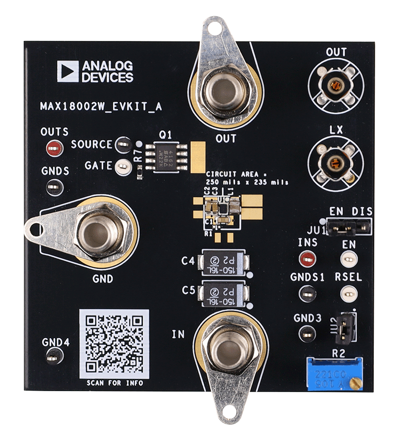
  • 1.8V to 5.5V Input Voltage
  • Test Points for INS, OUTS, and GNDS
  • Sense Sockets at LX and OUT
  • Output Voltage Adjustable Between 2.5V to 5.5V (in 100mV steps)

Product Details

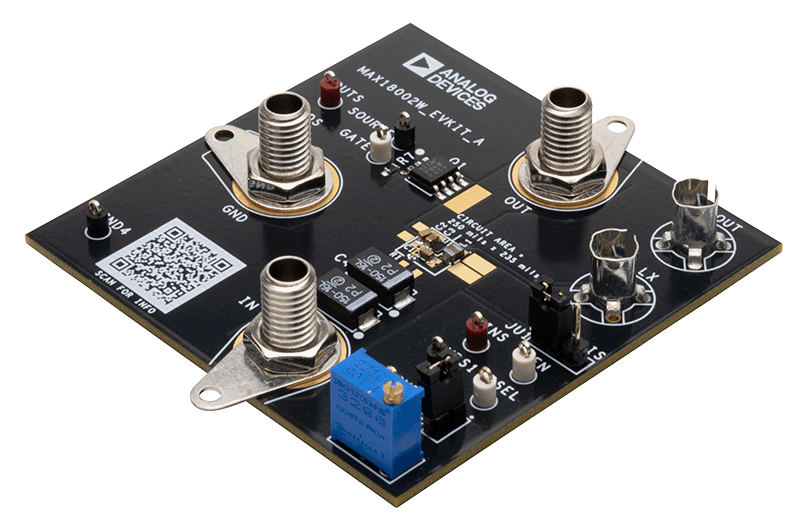
The MAX18002 evaluation kit (EV kit) is a fully assembled and tested printed circuit board (PCB) that demonstrates the MAX18002 series of boost converters. The MAX18002 series has an input range of 0.5V to 5.5V, with a switch current limit of 3.6A and output voltage adjustable between 2.5V and 5.5V (ultrasonic mode (USM) and nanopower mode disabled for VOUT > 5V).

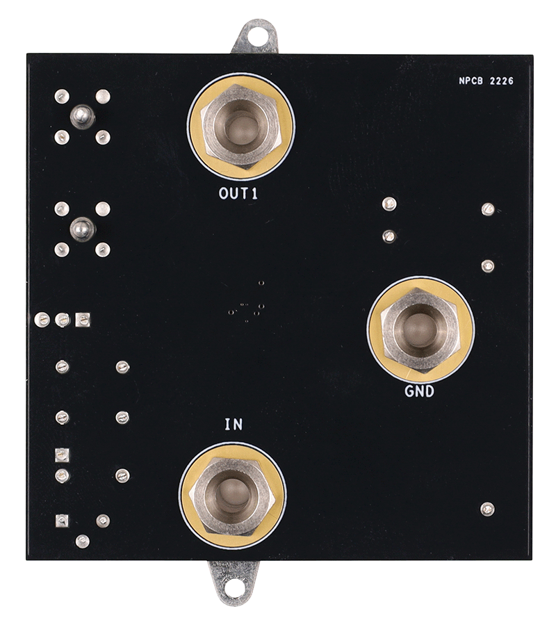
The EV kit can be ordered with MAX18000AWT+ (nanopower version) and MAX18002AWT+ (USM version). It is equipped with test points and jumpers for testing most of the functionality of the device. There are probing holes on critical nodes (OUT and LX) for precise measurements.

MAX18002EVKIT
Evaluation Kit for MAX18000 and MAX18002 in WLP Package
MAX18002WEVKIT Angle MAX18002WEVKIT Probe Angle MAX18002WEVKIT Top MAX18002WEVKIT Bottom

Latest Discussions

Recently Viewed