LT3595
Info: : PRODUCTION
searchIcon
cartIcon

LT3595

16 Channel Buck Mode LED Driver

Show More showmore-icon

Info: : PRODUCTION tooltip
Part Models 2
1ku List Price Starting From $7.50
Features
  • 4.5V to 45V Input Supply Range
  • Up to 50mA LED Current per Channel
  • 100mA, 45V Internal Switches
  • 8% Relative LED Current Match at 20mA
  • 16 Independent LED Channels
  • 5000:1 True Color PWM Dimming Range
  • LEDs Disconnected in Shutdown
  • Internal Schottky Diodes
  • Low Quiescent Current
  • 2MHz Switching Frequency
  • RSET Pin Sets Master LED Current
  • Typical Efficiency: 92%
  • Open LED Detection and Thermal Protection
  • 56-Pin 5mm × 9mm × 0.75mm QFN Package
Additional Details
show more Icon

The LT3595 is a high performance LED Driver designed to drive sixteen independent channels of up to 10 LEDs at currents up to 50mA. Series connection of the LEDs provides identical LED currents resulting in uniform brightness. Power switches, Schottky diodes, and compensation components are all internal, providing a small converter footprint and lower component cost. The high 2MHz switching frequency permits the use of tiny, low profi le inductors and capacitors. A fixed frequency, current mode architecture results in stable operation over a wide range of supply and output voltage.

A single external resistor sets the LED current for all sixteen channels, and dimming is then controlled for each channel by pulse width modulating the individual PWM pins. Relative current matching among the sixteen drivers is 8% and the PWM dimming range is 5000:1. The part is available in a 5mm x 9mm x 0.75mm 56-pin QFN package.

Applications

  • LED Video Billboards
  • LCD Televisions
  • Stadium and Advertising Displays
Part Models 2
1ku List Price Starting From $7.50

close icon

Documentation

Part Model Pin/Package Drawing Documentation CAD Symbols, Footprints, and 3D Models
LT3595EUHH#PBF
  • HTML
  • HTML
LT3595EUHH#TRPBF
  • HTML
  • HTML

Software & Part Ecosystem

Evaluation Kits 1

reference details image

DC1199A

LT3595EUHH Demo Board | 16-Channel Buck Mode LED Driver, 15V ≤ VIN ≤ 45V, VLED up to 12V @ 30mA (x16)

zoom

DC1199A

LT3595EUHH Demo Board | 16-Channel Buck Mode LED Driver, 15V ≤ VIN ≤ 45V, VLED up to 12V @ 30mA (x16)

LT3595EUHH Demo Board | 16-Channel Buck Mode LED Driver, 15V ≤ VIN ≤ 45V, VLED up to 12V @ 30mA (x16)

Product Detail

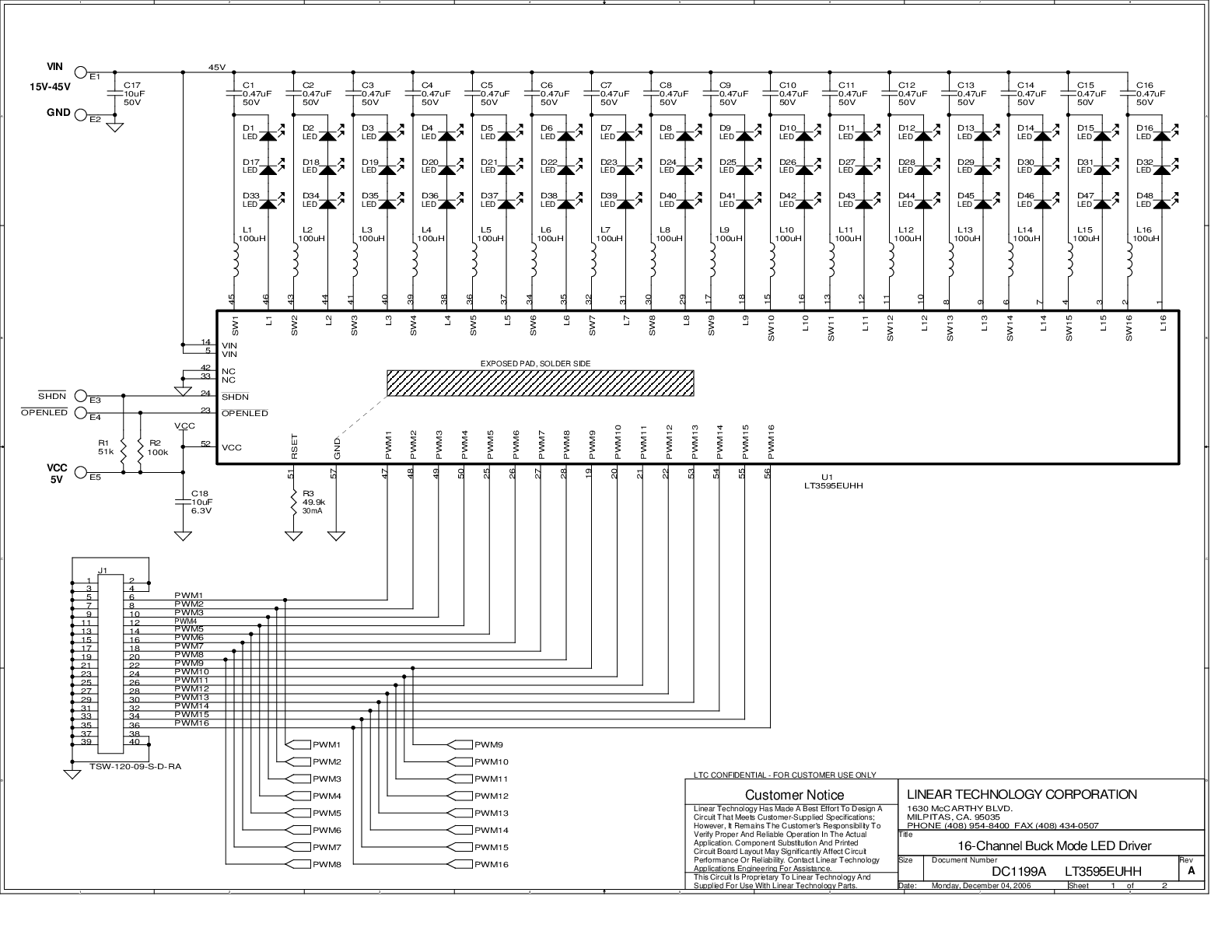
Demonstration circuit 1199A is a 16-Channel Buck Mode LED Driver featuring the LT3595EUHH. The circuit is optimized to drive 16 channels of three series LEDs at 30mA, though the LT3595 is capable of driving up to 10 LEDs at 50mA per channel. Each channel has three series white LEDs and they are stuffed on the PCB. The LT3595 features a wide input voltage range, integrated components, externally set LED current, high pwm dimming range, high efficiency, shutdown, open LED protection, and 2MHz switching frequency.


The 100mA, 45V fully integrated switches help drive up to 10 LEDs per channel in series at 50mA each. Internal catch diodes reduce external component count and circuit size. PWM dimming is as high as 1000:1 at 100Hz over the entire input voltage range.


There are three input power terminals: VIN ranges from 15V up to 45V and is used for powering the LEDs, VCC powers the LT3595 and the pwm gates, and µVIN (6-12V) powers the onboard PIC microprocessor. The PIC allows the board to demonstrate some preprogrammed patterns and PWM dimming. Although the range of the LT3595 VCC pin goes down to 3V, 5V is needed for the PWM signal gates to work properly with the PIC.

Tools & Simulations 1

LTspice® is a powerful, fast and free simulation software, schematic capture and waveform viewer with enhancements and models for improving the simulation of analog circuits.

To launch ready-to-run LTspice demonstration circuits for this part:

Step 1: Download and install LTspice on your computer.

Step 2: Click on the link in the section below to download a demonstration circuit.

Step 3: If LTspice does not automatically open after clicking the link below, you can instead run the simulation by right clicking on the link and selecting “Save Target As.” After saving the file to your computer, start LTspice and open the demonstration circuit by selecting ‘Open’ from the ‘File’ menu.

Recently Viewed